
How to
Connecting SpaceLogic Sensor Devices to an MP Controller
You connect SpaceLogic Sensor devices to an MP controller to provide the sensor devices with power and communication from the controller.
The MP controller sensor bus allows SpaceLogic Sensor devices to be connected to the controller.

Location of the Sensor Bus port on different MP controllers
When connecting SpaceLogic Sensor devices to the sensor bus through a daisy-chain configuration, the sensor bus ports on the SpaceLogic Sensor are interchangeable.
|
Description |
Model Number |
Power (mW) |
|
Sensor base with temperature sensor |
SXWSBTXXXSXX |
90 |
|
Sensor base with temperature and humidity sensors |
SXWSBTHXXSXX |
90 |
|
Sensor base with temperature and CO 2 sensors |
SXWSBTXCXSXX |
490 |
|
Sensor base with temperature, humidity, and CO 2 sensors |
SXWSBTHCXSXX |
490 |
|
Blank cover |
SXWSCBXSELXn a |
0 |
|
Blank cover with occupancy sensor |
SXWSCBPSELXn a |
20 |
|
3-button cover (buttons for override and setpoint control) |
SXWSC3XSELXn a |
190 |
|
3-button cover (buttons for override and setpoint control) with occupancy sensor |
SXWSC3PSELXn a |
210 |
|
Touchscreen display cover |
SXWSCDXSELXn a |
190 |
|
Touchscreen display cover with occupancy sensor |
SXWSCDPSELXn a |
210 |
|
Touchscreen display cover with light control buttons |
SXWSC2XSELXn a |
190 |
|
Touchscreen display cover with light control buttons and occupancy sensor |
SXWSC2PSELXn a |
210 |
|
Touchscreen display cover with light and blind control buttons |
SXWSC4XSELXn a |
190 |
|
Touchscreen display cover with light and blind control buttons and occupancy sensor |
SXWSC4PSELXn a |
210 |
|
Complete SpaceLogic Sensor model with temperature sensor, buttons for override and setpoint control, and LCD display cover |
SXWSATXXXSLn a |
80 |
|
Complete non-communicating b SpaceLogic Sensor model with resistive temperature sensor (10 kohm type 3 thermistor) and blank cover |
SLAnXXX c SXWSATXXXRXX d |
0 |
|
SpaceLogic Bluetooth Adapter e |
SXWBTAECXX10001 |
300 |
- The last character (“n”) of this model number indicates the housing: X (Medium matte white), W (Optimum glass white), or B (Optimum glass black).
- The SpaceLogic resistive temperature sensor is not designed to be connected to the sensor bus, but instead is connected to I/O points/terminals on the BACnet/IP controller using a two-wire connection.
- The fourth character (“n”) of this model number indicates the housing: S (Medium matte white), W (Optimum glass white), or B (Optimum glass black).
- The model number SXWSATXXXRXX is replaced by SLASXXX.
- Connect the SpaceLogic Bluetooth Adapter to the SpaceLogic Sensor for temporary commissioning and servicing only.
To summarize the power conditions, the sensor bus supports the following key SpaceLogic Sensor combinations:
Blank covers: Up to four sensors of any combination of sensor base types
3-button and touchscreen covers:
Up to two sensor bases with CO 2 option
Up to four sensor bases without CO 2 option
SpaceLogic LCD temperature sensors: Up to four sensors are supported

Examples with one SpaceLogic Sensor and four SpaceLogic Sensor devices connected to an MP controller in a daisy-chain configuration
Each SpaceLogic Sensor has two 2-position DIP switches, which are used to give the sensor a unique address on the sensor bus. An incorrectly configured or improper DIP switch can cause two sensors to have the same address on the sensor bus, which means that both sensors will be offline. For more information, see SpaceLogic Sensors .
SpaceLogic Sensor devices connected to the sensor bus through a daisy-chain configuration can be assigned addresses regardless of the order in which the sensors appear in the daisy chain. For example, sensor number 1 can have the address 6, sensor number 2 can have the address 4, and so on.
Install the SpaceLogic Sensor and connect a Cat 5 (or higher) unshielded, straight-through wired cable with eight conductors (four twisted pairs) to one of the two RJ45 receptacles on the sensor. Use a cable with the wire size (cross-sectional area) 22 to 26 AWG (0.34 to 0.14 mm²).
For more information, see SpaceLogic Sensors - SXWS Sensor Base - Installation Instructions .
For more information, see SpaceLogic Sensors - SXWS LCD Temperature Sensors - Installation Instructions .
Connect the other end of the cable to the Sensor Bus port on the MP controller.
action_zoom_plus_stroke 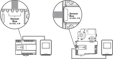
When an additional SpaceLogic Sensor is needed, install the sensor and connect the other end of the cable to the unused RJ45 receptacle on the previous sensor.
Note:When connecting SpaceLogic Sensor devices to the MP controller's sensor bus through a daisy-chain configuration, it does not matter if the incoming and outgoing cables are connected to one or the other sensor bus port on the SpaceLogic Sensor.
action_zoom_plus_stroke 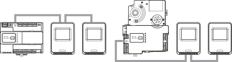
Repeat step 3 to install a third and fourth SpaceLogic Sensor, if the power constraints of the sensor bus allow this for the selected combination of cover and sensor base type.
Ensure that the two 2-position address DIP switches on each SpaceLogic Sensor are configured to give the sensor a unique address on the sensor bus.
For more information, see SpaceLogic Sensors - SXWS Sensor Base - Installation Instructions .
For more information, see SpaceLogic Sensors - SXWS LCD Temperature Sensors - Installation Instructions .
For more information, see Configuring a SpaceLogic Sensor .
 MP-C Controllers
MP-V Controllers
MP Controller Sensor Bus
MP-C Controllers
MP-V Controllers
MP Controller Sensor Bus
 SpaceLogic Sensor or MP Controller Sensor Bus Is Not Operational
Configuring a SpaceLogic Sensor
SpaceLogic Sensor or MP Controller Sensor Bus Is Not Operational
Configuring a SpaceLogic Sensor