
How to
Connecting RP Controller Expansion Modules and Multi-sensors to RP-C
You connect RP controller expansion modules and multi-sensors to the RP-C room bus to provide the devices with power and communication from the RP-C controller.
The RP controller room bus allows RP controller expansion modules to be connected to the controller for people counting, motion detection, luminosity and sound pressure level measurements, Bluetooth Low Energy based applications, and control of electric lights and window blinds.
The maximum total length of the room bus is 72 m (236 ft). The room bus uses a Cat 5 (or higher) unshielded, straight-through wired cable with eight conductors (four twisted pairs) and RJ45 connectors. The wire size (cross-sectional area) should be 22 to 26 AWG (0.34 to 0.14 mm²). When the RP-C controller is installed in a space that handles conditioned air or return air, the room bus cables and IP network cables frequently must be plenum-rated to meet applicable building codes. For more information, see Wiring .
By default, the RP-C controller's RS-485 Com B port is configured and allocated for the room bus. For more information, see RP-C Communication Ports .

Location of the Room Bus ports and address switches on the RP-C controllers and RP controller expansion modules
Restrictions for Connecting RP Controller Expansion Modules to the RP-C Room Bus
The maximum number of RP controller expansion modules that can be connected to the RP-C room bus, and the restrictions that apply to certain types of the modules, vary depending on the RP-C controller model. In this respect, the RP-C controller models are divided in the following two categories:
RP-C-12A-F-24V, RP-C-12B-F-24V, RP-C-12C-F-24V, and RP-C-16A-F-230V
RP-C-16B-F-24V and RP-C-16B-F-230V
For more information, see RP-C Models .
The restrictions listed below only apply to Connected Room Solutions for Buildings. For information on what restrictions apply to Connected Room Solutions for Hotels, see the supplementary document Architecture Guidelines – Hotel Application.
To the room bus of the RP-C-12A-F-24V, RP-C-12B-F-24V, RP-C-12C-F-24V, and RP-C-16A-F-230V controller models, you can connect a single RP controller expansion module, or you can connect up to six devices in a daisy-chain configuration.
When connecting devices to the RP-C room bus through a daisy-chain configuration, the room bus ports on the device are interchangeable.
The RP-C room bus supports up to six connected RP controller expansion modules with the following restrictions:
Maximum of two DALI light modules
Maximum of two SMI blind modules
Maximum of four Multi-sensor or Insight-Sensor devices

Example of supported combination of RP controller expansion modules on the RP-C room bus
Each RP controller expansion module has a rotary switch, which is used to give the device a unique address on the room bus. An RP controller expansion module can be given any address in the range of 1 to 6. Configuring the address 0 means that the device enters maintenance mode and goes offline. Configuring an address in the range of 7 to 9 also means that the device goes offline. For more information, see RP Controller Expansion Module Room Bus Addressing . An incorrectly configured switch can cause two devices to have the same address on the room bus, which means that both devices will be offline.
|
Address |
Description |
|
0 |
Maintenance mode. Device offline. |
|
1 to 6 |
Valid addresses for devices connected to the room bus of the RP-C-12A-F-24V, RP-C-12B-F-24V, RP-C-12C-F-24V, and RP-C-16A-F-230V controller models. |
|
7 to 9 |
Addresses not supported by the the RP-C-12A-F-24V, RP-C-12B-F-24V, RP-C-12C-F-24V, and RP-C-16A-F-230V controller models or the EcoStruxure Building Operation software. Device offline. |
Devices connected to the RP-C room bus through a daisy-chain configuration can be assigned addresses regardless of the order in which the devices appear in the daisy chain. For example, device number 1 can have the address 6, device number 2 can have the address 4, and so on.
An RP controller expansion module can be put into different maintenance modes in which the device is either offline or online. For more information, see RP Controller Expansion Module Maintenance Modes .
To the room bus of the RP-C-16B-F-24V and RP-C-16B-F-230V controller models, you can connect a single RP controller expansion module, or you can connect up to nine devices in a daisy-chain configuration.
When connecting devices to the RP-C room bus through a daisy-chain configuration, the room bus ports on the device are interchangeable.
The RP-C room bus supports up to nine connected RP controller expansion modules with the following restrictions:
Maximum of two DALI light modules
Maximum of two SMI blind modules
Maximum of seven Multi-sensor or Insight-Sensor devices

Example of supported combination of RP controller expansion modules on the RP-C room bus
Each RP controller expansion module has a rotary switch, which is used to give the device a unique address on the room bus. An RP controller expansion module can be given any address in the range of 1 to 9. Configuring the address 0 means that the device enters maintenance mode and goes offline. For more information, see RP Controller Expansion Module Room Bus Addressing . An incorrectly configured switch can cause two devices to have the same address on the room bus, which means that both devices will be offline.
|
Address |
Description |
|
0 |
Maintenance mode. Device offline. |
|
1 to 9 |
Valid addresses for devices connected to the room bus of the RP-C-16B-F-24V and RP-C-16B-F-230V controller models. |
Devices connected to the RP-C room bus through a daisy-chain configuration can be assigned addresses regardless of the order in which the devices appear in the daisy chain. For example, device number 1 can have the address 6, device number 2 can have the address 4, and so on.
An RP controller expansion module can be put into different maintenance modes in which the device is either offline or online. For more information, see RP Controller Expansion Module Maintenance Modes .
Install the RP controller expansion module or multi-sensor and connect a Cat 5 (or higher) unshielded, straight-through wired cable with eight conductors (four twisted pairs) to one of the two RJ45 receptacles on the module or multi-sensor. Use a cable with the wire size (cross-sectional area) 22 to 26 AWG (0.34 to 0.14 mm²).
action_zoom_plus_stroke 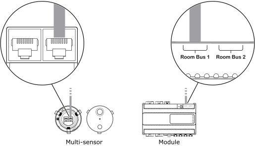
Connect the other end of the cable to the RP-C controller's RS-485 port that is configured for the room bus.
Note:By default, the RS-485 Com B port is configured for the room bus.
action_zoom_plus_stroke 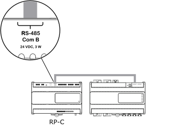
When an additional RP controller expansion module or multi-sensor is needed, install the device and connect the other end of the cable to the unused RJ45 receptacle on the previous module or multi-sensor.
Note:When connecting devices to the RP controller room bus through a daisy-chain configuration, the room bus ports on the device are interchangeable.
action_zoom_plus_stroke 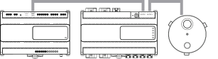
Repeat step 3 to install additional devices up to the maximum number of six devices of the supported combination of RP controller expansion modules and multi-sensors. For more information, see RP-C Room Bus .
Ensure that the rotary switch on each RP controller expansion module and multi-sensor is configured to give the device a unique room bus address in the range of 1 to 6.
For more information, see Configuring the Room Bus Address for an RP Controller Expansion Module .
For more information, see Configuring the Room Bus Address for an RP Controller Expansion Sensor Module .
For more information, see RP Controller Expansion Module Room Bus Addressing .
 RP-C Controllers
RP-C Room Bus
RP-C Communication Ports
Configuring the Room Bus Address for an RP Controller Expansion Module
Configuring the Room Bus Address for an RP Controller Expansion Sensor Module
RP Controller Expansion Module Room Bus Addressing
RP-C Controllers
RP-C Room Bus
RP-C Communication Ports
Configuring the Room Bus Address for an RP Controller Expansion Module
Configuring the Room Bus Address for an RP Controller Expansion Sensor Module
RP Controller Expansion Module Room Bus Addressing