
Concept
RP-C-EXT-BL-SMI-2-LV-PD
The RP-C-EXT-BL-SMI-2-LV-PD SMI blind module connects to the RP-C room controllers and provides I/O expansion for control of DC low-voltage motors (drives) with SMI LoVo (Standard Motor Interface for low-voltage applications).
The SMI low-voltage blind module enables control and power supply (24 VDC) of motorized venetian blinds, roller blinds, pleated blinds, and other shade products (typically for interior use).
The SMI blind module is part of the RP controller expansion modules for connected room solution and can be combined with other modules from this product range.

RP-C-EXT-BL-SMI-2-LV-PD – SMI low-voltage blind module
SMI LoVo Blind Outputs
The SMI low-voltage blind modules have two Blind outputs for control of motorized window blinds (drives) that are powered by 24 VDC. The Standard Motor Interface (SMI), LoVo version for DC low-voltage drives, is used to control the blind motors.
For more information, see SMI LoVo Blind Outputs .
RP Controller Expansion Module Digital Inputs
The RP controller expansion modules have digital inputs that can be used for sensing of dry contacts:
The light modules, blind modules, and the RP-C-EXT-REL-4 relay module have four digital inputs, which can be used in applications such as interfacing with light switches and window contacts.
The CRS-HH-REL-10 relay module has 12 digital inputs suitable for dry contact monitoring of switches and push buttons used for lighting control, window and door positions, and other functions in the hotel room.
For more information, see RP Controller Expansion Module Digital Inputs .
RP Controller Expansion Module Built-in Power Supply
The RP controller expansion light modules with power distribution capability, low-voltage blind modules, and SMI blind modules have a built-in power supply that can accommodate a nominal input voltage of 230 VAC at 50/60 Hz. Light modules without power distribution capability can accommodate a nominal input voltage of 100 to 277 VAC at 50/60 Hz.
For more information, see RP Controller Expansion Module Built-in Power Supply .
RP Controller Expansion Module Energy Metering
RP controller expansion modules with power distribution capability support energy metering, which means that the module can measure the electrical energy consumption and power demand for the equipment connected to and supplied by the module.
For more information, see RP Controller Expansion Module Energy Metering .
RP Controller Expansion Module Memory
RP controller expansion modules have two types of memory, flash memory and RAM.
For more information, see RP Controller Expansion Module Memory .
SMI Blind Modules Supported Building Standards
The SMI blind modules comply to version 3.0 of the SMI specification.
For more information, see SMI Blind Modules Supported Building Standards .
RP Controller Expansion Module Communication Ports
The RP controller expansion modules have two room bus ports (RJ45 receptacles), which enable connection to the RP-C controller and other expansion modules on the room bus through a daisy-chain configuration.
For more information, see RP-C Room Bus .
RP Controller Expansion Module Address Switch
Each RP controller expansion module has a rotary switch, which is used to give the device a unique address on the room bus.
For more information, see RP-C Room Bus .
RP-C Room Bus
The RP controller room bus allows RP controller expansion modules to be connected to the controller for people counting, motion detection, luminosity and sound pressure level measurements, Bluetooth Low Energy based applications, and control of electric lights and window blinds.
For more information, see RP-C Room Bus .
RP Controller Expansion Module Pluggable Connectors
The RP controller expansion modules have PCB mounted connectors for the power input, outputs, and digital inputs. The PCB mounted connectors mate with pluggable connectors:
The light modules, blind modules, and the RP-C-EXT-REL-4 relay module have mechanically keyed and color-coded connectors, which allows the matching external connectors to be plugged in on site quickly and easily.
The CRS-HH-REL-10 relay module has PCB header connectors for pluggable screw terminal blocks, which are easy to install and remove from the device.
For more information, see RP Controller Expansion Module Pluggable Connectors .
RP Controller Expansion Module LEDs
There is one or more LEDs on the front panel of the RP controller expansion modules.
For more information, see RP Controller Expansion Module LEDs .
RP Controller Expansion Module Set Button
All RP controller expansion modules have a Set button on the front. The Set button is reserved for future use.
For more information, see RP Controller Expansion Module Set Button .
RP Controller Expansion Module Device Installation
The RP controller expansion module can be installed on a DIN rail or flat surface.
For more information, see RP Controller Expansion Module Device Installation .
Wiring
The wiring recommendations provide guidance regarding wiring of the Central IO modules, automation servers, BACnet/IP devices, RP controller expansion modules, and Operator Display.
For more information, see Wiring .
RP Controller Expansion Module Maintenance Modes
The RP controller expansion modules support different modes that can be used for maintenance purposes.
For more information, see RP Controller Expansion Module Maintenance Modes .
BACnet/IP Device Firmware Management
Using WorkStation, you can update the firmware of multiple BACnet/IP devices and their attached SpaceLogic Sensor devices and RP controller expansion modules at the same time with minimum downtime. In particular, the universal upgrade package simplifies the update process and requires minimal user involvement and coordination.
SpaceLogic Sensor devices and RP controller expansion modules are supported by the RP controller.
For more information, see BACnet/IP Device Firmware Management .
RP Controller Expansion Module Regulatory Compliance and Approvals
This section provides information on regulatory compliance and approvals for the RP controller expansion modules.
For more information, see RP Controller Expansion Light, Blind, and Relay Modules Regulatory Compliance and Approvals .
Specifications
| Electrical | |
Nominal voltage
|
230 VAC
|
Operating voltage range
|
+/-10 %
|
Frequency
|
50/60 Hz
|
Power consumption
|
75 VA
|
Room bus power consumption
|
0.3 W (24 VDC)
|
Protection
|
Maximum 16 A external fuse (circuit breaker) is needed
|
Overvoltage category
|
III
|
| Onboard 24 VDC power supply | |
| RP-C-EXT-BL-SMI-2-LV-PD has an onboard 24 VDC power supply that is used to power the blind outputs. | |
Nominal voltage
|
24 VDC
|
Maximum supply current
|
1.3 A
|
Protection
|
Short-circuit protection
|
| Environment | |
Ambient temperature, operating
|
0 to 40 °C (32 to 104 °F)
|
Ambient temperature, storage
|
-20 to +70 °C (-4 to +158 °F)
|
Humidity
|
20 to 90 % RH non-condensing
|
Pollution degree
|
2
|
| Material | |
Plastic flame rating
|
UL94 V-0
|
Ingress protection rating
|
IP 20
|
| Mechanical | |
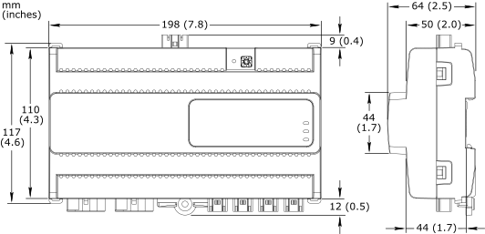
Dimensions
|
198 W x 110 H x 64 D mm (7.8 W x 4.3 H x 2.5 D in.)
|
|
|
Weight
|
0.439 kg (0.968 lb)
|
Installation
|
DIN rail or flat surface
a
|
| a) For the SMI low-voltage blind module certain restrictions apply to the installation orientation. For more information, see RP Controller Expansion Module Device Installation . | |
Connectors
|
Power input: 1 x 3-pin Wieland GST15i3 connector
|
Blind outputs: 2 x 5-pin Wieland GST15i5 connector
|
|
Digital inputs: 4 x 2-pin Wieland GST15i2 connector
|
|
| Communication ports | |
Room bus
|
RS-485
|
Dual RJ45 ports for daisy-chain configurations
|
|
Use a Cat 5 (or higher) cable
|
|
Maximum total length of the room bus: 72 m (236 ft)
|
|
Room bus protection
|
Transient voltage suppressors on communication and power signals
|
| Hardware | |
CPU type
|
ARM Cortex-M4 single-core
|
Frequency
|
80 MHz
|
SRAM (embedded)
|
320 KB
|
Flash memory (embedded)
|
512 KB
|
NOR flash memory
|
16 MB
|
Status indicator
|
LED (green and red) that shows the status of the device
|
Blind status indicator
|
One status LED (green) for each output
|
Address switch
|
Rotary switch 0 to 9
|
Set button
|
Push-button switch
|
| Energy metering | |
| Energy consumption measurement | |
| The energy consumption is measured in Wh, shared by the two outputs. | |
Accuracy class (according to IEC 61557-12)
|
Active energy measurement: Class 1
|
Typical measurement accuracy at room temperature
|
0.5 to 2 W: 5%
|
2 to 30 W: 1%
|
|
| Blind outputs | |
| SMI LoVo motor control outputs for 24 VDC powered blinds motors. | |
Outputs
|
2, Blind 1 to Blind 2
|
Output terminals
|
I+, I-, 0 V, and 24 V
|
SMI version
|
3.0
|
Number of SMI channels
|
1
|
Maximum total number of blind motors (drives)
|
16
|
Power distribution
|
24 VDC
|
Maximum 1 A load per output
|
|
Maximum 1.3 A total load for the 2 outputs
|
|
Maximum 2 A starting current (<100 ms) per output
|
|
| Digital inputs | |
Inputs
|
4, DI1 to DI4
|
Range
|
Dry contact, 0 to 5.0 VDC, 2.2 mA, SELV (Safety Extra-Low Voltage)
|
Internal Configuration
The RP-C-EXT-BL-SMI-2-LV-PD internal configuration with regards to the signal ground is shown in the following figure.

RP-C-EXT-BL-SMI-2-LV-PD internal configuration
Hardware Overview
RP Controller Expansion Modules
Blind Modules
SMI LoVo Blind Outputs
RP Controller Expansion Module Digital Inputs
RP Controller Expansion Module Built-in Power Supply
RP Controller Expansion Module Energy Metering
RP Controller Expansion Module Memory
SMI Blind Modules Supported Building Standards
RP-C Room Bus
RP Controller Expansion Module Pluggable Connectors
RP Controller Expansion Module LEDs
RP Controller Expansion Module Set Button
RP Controller Expansion Module Device Installation
Wiring
RP Controller Expansion Module Maintenance Modes
BACnet/IP Device Firmware Management
RP Controller Expansion Light, Blind, and Relay Modules Regulatory Compliance and Approvals