
Concept
KNX Modbus Gateway RP-C-EXT-KNX
The KNX Modbus gateway RP-C-EXT-KNX connects to the RP-C controllers and provides an interface between the controller and KNX devices such as push-buttons, sensors, and control units for lights, blinds, and room temperature.
The KNX Modbus gateway allows bi-directional control and monitoring of all parameters and functions of the connected KNX devices. Up to 250 KNX data points (10 KNX devices) can be connected to the KNX Modbus gateway.
The KNX Modbus gateway is a Modbus to KNX interface that connects to one of the RP-C controller's configurable RS-485 ports. The Modbus RTU protocol is used for the communication between the RP-C controller and the KNX Modbus gateway. The RP-C controller acts the Modbus client and the KNX Modbus gateway as a server. The RP-C controller also provides 24 VDC power supply to the KNX Modbus gateway through the RS-485 interface. Maximum one KNX Modbus gateway can be connected to each RP-C controller.
The KNX Modbus gateway provides a galvanic isolation between the RP-C Modbus network and the KNX bus. The KNX Modbus gateway can be used with a standard Schneider Electric KNX power supply to power the KNX devices on the KNX bus.
The KNX Modbus gateway can be programmed through ETS© for installation, configuration, and commissioning of KNX devices. The assignment between KNX objects and Modbus registers is configured in ETS. The completed configuration in ETS is exported to a JSON file, which is then imported into the EcoStruxure Building Operation software to create the Modbus input and output points for the Modbus device proxy object (representation of the KNX Modbus gateway). For more information, see ETS and the KNX Modbus Gateway .
The KNX Modbus gateway is designed for installation on a DIN rail.
The KNX Modbus gateway has two push-buttons and three LEDs on the front to enable local operation of the device and status indication.

KNX Modbus gateway RP-C-EXT-KNX
RP-C Modbus
The RP-C Modbus network allows standard Modbus devices and the KNX Modbus gateway (RP-C-EXT-KNX) to be connected to the controller.
For more information, see RP-C Modbus .
KNX Modbus Gateway Screw Terminals and Connector
The KNX Modbus gateway (RP-C-EXT-KNX) is equipped with two 3-position pluggable screw terminal blocks for connection to the RP-C Modbus (RS-485) network and a 2-pole PCB connector for connection to the KNX bus.
For more information, see KNX Modbus Gateway Screw Terminals and Connector .
KNX Modbus Gateway LEDs
There are three LEDs on the front of the KNX Modbus gateway (RP-C-EXT-KNX) and one LED above the front. The LEDs indicate different types of status and modes.
For more information, see KNX Modbus Gateway LEDs .
KNX Modbus Gateway Buttons
There are two push-buttons on the front of the KNX Modbus gateway (RP-C-EXT-KNX) and one button above the front. The buttons are used to activate or deactivate various modes.
For more information, see KNX Modbus Gateway Buttons .
KNX Modbus Gateway Programming Mode
When the KNX Modbus gateway (RP-C-EXT-KNX) is in programming mode, you can assign an individual address to the device on the KNX bus.
For more information, see KNX Modbus Gateway Programming Mode .
KNX Modbus Gateway Manual Operation Mode
The manual operation mode enables you to perform two types of operations:
KNX object synchronization
KNX read operation
For more information, see KNX Modbus Gateway Manual Operation Mode .
KNX Modbus Gateway Device Installation
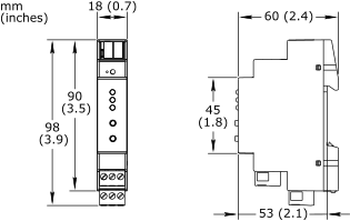
The KNX Modbus gateway (RP-C-EXT-KNX) is designed for installation on a DIN rail. The width of the device is 1 unit (18 mm or 0.7 inch).
For more information, see KNX Modbus Gateway Device Installation .
Wiring
The wiring recommendations provide guidance regarding wiring of the Central IO modules, automation servers, BACnet/IP devices, RP controller expansion modules, and Operator Display.
For more information, see Wiring .
KNX Modbus Gateway Regulatory Compliance and Approvals
This section provides information on regulatory compliance and approvals for the KNX Modbus gateway (RP-C-EXT-KNX).
For more information, see KNX Modbus Gateway Regulatory Compliance and Approvals .
Specifications
| Electrical | |
DC input supply voltage
|
24 VDC
|
Powered by the RP-C
|
|
Maximum power consumption
|
<0.24 W from the KNX bus
|
<0.24 W from the RP-C
|
|
| Environment | |
Ambient temperature, operating
|
-5 °C to +45 °C (23 °F to +113 °F)
|
Ambient temperature, storage
|
-25 to +70 °C (-13 to +158 °F)
|
Humidity
|
5 to 93 % RH non-condensing
|
| Material | |
Ingress protection rating
|
IP 20
|
| Mechanical | |
Dimensions
|
18 W x 90 H x 60 D mm (0.7 W x 3.5 H x 2.4 D in.)
|
|
|
Weight
|
50 g (1.76 oz)
|
Installation
|
DIN rail
|
| RP-C Modbus communications | |
Communication protocol (configurable)
|
Modbus RTU
|
Electrical interface
|
RS-485
|
Maximum total length of the RP-C Modbus (RS-485) network: 72 m (236 ft)
|
|
| KNX bus communications | |
Transmission media
|
Twisted pair (TP)
|
Maximum APDU length
|
55
|
Device model
|
System B
|
| Hardware | |
CPU type
|
ARM Cortex-M0+ single-core
|
Frequency
|
14.7456 MHz
|
SRAM (embedded)
|
32 KB
|
Flash memory (embedded)
|
256 KB
|
Status indicator
|
LED (green and red) that shows the KNX communication status
|
LED (green and red) that shows the Modbus RTU communication status
|
|
LED (green and red) that shows the device mode (operating or programming mode)
|
|
One LED (red) for programming mode
|
|
Buttons
|
One push-button for synchronization of KNX objects (writing all KNX group objects)
|
One push-button for reading all KNX group objects
|
|
One button for programming mode
|
|
Connectors
|
4-conductor KNX connectors with PUSH WIRE® connection, 2-pole, dark gray/red
|
Terminal blocks
|
3-position pluggable screw terminal block for power supply from the RP-C
|
3-position pluggable screw terminal block for Modbus communication with the RP-C
|
|
Wire cross-sectional area: 0.34 to 2.5 mm
2
(22 to 14 AWG)
|
|
Hardware Overview
KNX Modbus Gateway Screw Terminals and Connector
KNX Modbus Gateway LEDs
KNX Modbus Gateway Buttons
KNX Modbus Gateway Programming Mode
KNX Modbus Gateway Manual Operation Mode
KNX Modbus Gateway Device Installation
ETS and the KNX Modbus Gateway
ETS Database for the KNX Modbus Gateway
Wiring
KNX Modbus Gateway Regulatory Compliance and Approvals