
Specifications
RTD-DI-16

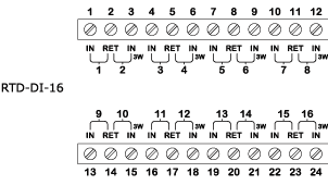
Central IO module RTD-DI-16
Introduction
SpaceLogic* RTD-DI-16 Central IO module is an RTD/digital input, 16-channel I/O module.
The inputs of RTD-DI-16 can be configured to read seven different types of inputs:
2-wire RTD temperature
3-wire RTD temperature
2-wire RTD resistive
3-wire RTD resistive
Digital
Counter
Resistive
RTD-DI-16 supports 3-wire configurations that consume two input channels. The number of channels available range between 8 to 16 depending on the number of 3-wire configurations that are used.
The inputs can be used for sensing multiple dry contact inputs in applications, such as equipment status monitoring or alarm point monitoring. As counter inputs, they are commonly used in energy metering applications.
The RTD inputs are ideal for temperature points in a building control system.
* Formerly known as SmartX.
Function
The modules are part of a modular system that delivers power and communications on a common bus. Connecting modules is a one-step process: just slide the modules together using the built-in connectors.
Each module can be separated from its terminal base to allow the site to be wired prior to the installation of the electronics. The patented locking mechanism serves as handles for removing the module from its base. All critical components have a protective cover that permits convection cooling to occur.

Two-piece design
Because critical applications require 24-hour operation, Schneider Electric designed the Central IO modules for hot-connection of terminal bases and hot-swapping of the modules to their bases. This design ensures continuous power and communication during service operations.
The auto-addressing feature helps eliminating the need for setting DIP switches or pressing commission buttons. Each module automatically knows its order in the chain and assigns itself accordingly – significantly reducing engineering and maintenance time.
Fasteners easily snap into a locked position for panel installation. The fastener has a quick-release feature for easy DIN-rail removal.
The Central IO module terminals are clearly labeled and protected by transparent covers. The input and output terminals are at the top and bottom of each module and are accessible for maintenance without removing the module. The EcoStruxure Building Operation WorkStation software can generate custom as-built labels for each module. Pre-perforated letter and A4 size label sheets are available as an accessory.
The SpaceLogic devices use built-in connectors for single row connectivity, side by side. If a panel size requires multiple rows, extension cords are available.
The Central IO module has a status indicator that denotes the health and status of the module.
Each input channel has a dedicated two color status LED. The LED can be configured to display either red or green for each input state.
Protection components on the inputs protect against high-voltage short-duration transient events.
Specifications
Input channels
|
16
|
| 3-wire RTDs require 2 inputs | |
DC input supply power
|
1.6 W
|
DC input supply voltage
|
24 VDC
|
| Environment | |
Ambient temperature, operating
|
0 to 50 °C (32 to 122 °F)
|
Ambient temperature, storage
|
-20 to +70 °C (-4 to +158 °F)
|
Maximum humidity
|
95 % RH non-condensing
|
| Material | |
Plastic flame rating
|
UL94-5VB
|
Enclosure
|
PC/ABS
|
Ingress protection rating
|
IP 20
|
| Mechanical | |
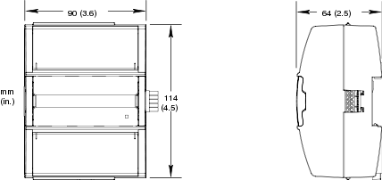
Dimensions including terminal base
|
90 W x 114 H x 64 D mm (3.6 W x 4.5 H x 2.5 D in.)
|
|
|
Weight including terminal base
|
0.269 kg (0.59 lb)
|
Weight excluding terminal base
|
0.146 kg (0.32 lb)
|
Terminal base
|
TB-IO-W1
|
| Agency compliances | |
Emission
|
RCM; BS/EN 61000-6-3; FCC Part 15, Sub-part B, Class B
|
Immunity
|
BS/EN 61000-6-2
|
Safety standards
|
BS/EN 61010-1; UL 916 C-UL US Listed
|
Product
|
BS/EN 61326-1
|
Smoke control product safety
|
UL 864
|
| Part numbers | |
RTD-DI-16, Central IO module
|
|
16 RTD/digital inputs
|
SXWRTD16X10001
|
TB-IO-W1, terminal base for Central IO module
|
|
(Required for each Central IO module)
|
SXWTBIOW110001
|
| Accessory part numbers | |
DIN-RAIL-CLIP, DIN-rail end clip
|
|
package of 25 pieces
|
SXWDINEND10001
|
PRINTOUT-A4-W1, printout sheets for terminal labels
|
|
A4 sheet size, 100 sheets, 18 labels per sheet
|
SXWTERLBL10011
|
PRINTOUT-LTR-W1, printout sheets for terminal labels
|
|
Letter sheet size, 100 sheets, 16 labels per sheet
|
SXWTERLBL10012
|
S-CABLE-L, S-cable extension cord for the I/O bus, L shaped connectors
|
|
1.5 m
|
SXWSCABLE10002
|
S-CABLE-L, S-cable extension cord for the I/O bus, L shaped connectors
|
|
0.75 m
|
SXWSCABLE10003
|
| Universal inputs | |
|
|
Absolute maximum ratings
|
-0.5 to +24 VDC
|
| RTD temperature | |
Reliability check
|
Yes
|
Supported RTDs
|
Pt100, Pt1000, Ni1000, LG-Ni1000, and JCI-Ni1000
|
| Pt100 | |
Range
|
-50 to +150 °C (-58 to +302 °F)
|
Measurement accuracy
|
+/-0.3 °C (+/-0.54 °F)
|
Resolution
|
0.03 °C (0.05°F)
|
| Pt1000 | |
Range
|
-50 to +150 °C (-58 to +302 °F)
|
Measurement accuracy
|
+/-0.2 °C (+/-0.36 °F)
|
Resolution
|
0.03 °C (0.05 °F)
|
| Ni1000 | |
Range
|
-50 to +150 °C (-58 to +302 °F)
|
Measurement accuracy
|
+/-0.1 °C (+/-0.18 °F)
|
Resolution
|
0.03 °C (0.05 °F)
|
| LG-Ni1000 | |
Range
|
-50 to +150 °C (-58 to +302 °F)
|
Measurement accuracy
|
+/-0.1 °C (+/-0.18 °F)
|
Resolution
|
0.03 °C (0.05 °F)
|
| JCI-Ni1000 | |
Range
|
-50 to +150 °C (-58 to +302 °F)
|
Measurement accuracy
|
+/- 0.1 °C (+/- 0.18 °F)
|
Resolution
|
0.03 °C (0.05 °F)
|
| RTD temperature wiring | |
Maximum wire resistance
|
20 ohm/wire (40 ohm total)
|
Maximum wire capacitance
|
60 nF
|
| The wire resistance and capacitance typically corresponds to a 200 m wire. | |
| RTD resistive | |
Reliability check
|
Yes
|
| 100 ohm | |
Range
|
50 to 220 ohm
|
Including wiring resistance
|
|
Measurement accuracy
|
+/-(0.08 + 2 x 10
-4
x R) ohm
|
| R = resistance in ohm | |
Resolution
|
0.01 ohm
|
| 1,000 ohm | |
Range
|
500 to 2,200 ohm
|
Including wiring resistance
|
|
Measurement accuracy
|
+/-(0.3 + 2 x 10
-4
x R) ohm
|
| R = resistance in ohm | |
Resolution
|
0.1 ohm
|
| RTD resistive wiring | |
Maximum wire capacitance
|
60 nF
|
| Digital | |
Range
|
Dry contact switch closure or open collector/open drain, 24 VDC, 2.4 mA
|
Minimum pulse width
|
120 ms
|
LED polarity
|
Software selectable, if the LED is activated when the input is high or low
|
LED color
|
Red or green, software selectable
|
| Counter | |
Range
|
Dry contact switch closure or open collector/open drain, 24 VDC, 2.4 mA
|
Minimum pulse width
|
20 ms
|
Maximum frequency
|
25 Hz
|
LED polarity
|
Software selectable, if the LED is activated when the input is high or low
|
LED color
|
Red or green, software selectable
|
| Resistive | |
Range
|
0 to 15,000 ohm
|
Accuracy
|
+/-(3 + 6 x 10
-4
x R) ohm
|
| R = resistance in ohm | |
Resolution
|
1 ohm
|
Reliability check
|
Yes
|
Maximum wire capacitance
|
60 nF
|
For protection from excess current that could be produced by field wiring, follow these instructions:
Connect one RET terminal on each of the Central IO modules to a common chassis/power ground rail in the control panel using a size 16 AWG (1.3 mm 2 ), or larger wire.
Individual 24 VDC power sources to the field must be current limited to maximum of 4 A for UL compliant installations, and no more than 6 A in other areas.
For more information on wiring, see the SpaceLogic Hardware Reference Guide.
UI-16
DI-16
AO-8 and AO-8-H
AO-V-8 and AO-V-8-H
DO-FA-12 and DO-FA-12-H
DO-FC-8 and DO-FC-8-H
UI-8/AO-4 and UI-8/AO-4-H
UI-8/AO-V-4 and UI-8/AO-V-4-H
UI-8/DO-FC-4 and UI-8/DO-FC-4-H