
Concept
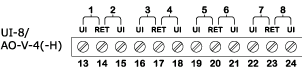
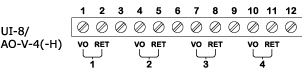
UI-8/AO-V-4 and UI-8/AO-V-4-H Central IO Modules
The UI-8/AO-4 and UI-8/AO-V-4 Central IO modules combine 8 universal inputs and 4 analog outputs.
Module names with an -H indicate the presence of Hand-Off-Auto override switches.
The override switches on Central IO modules with manufacturing date earlier than 2021-W26 must be disabled to remove the risk of an improper output. For more information, see Important Information on Central IO Modules with Manufacturing Date Earlier Than 2021-W26 .
The front panel includes a dedicated two-color (red and green) status LED for local monitoring of contact, counter, and supervised input types. You can configure the LED to display either red or green for each input or output state.

UI-8/AO-V-4-H Central IO Module
Universal inputs
The universal inputs of the UI-8/AO-V-4 and UI-8/AO-V-4-H Central IO modules are designed to read several different types of inputs.
Input types:
Digital
Counter
Supervised
Voltage
Current
Temperature
Resistive

Universal input internal configuration
Applied voltages beyond the absolute maximum ratings will cause over current in the protection component D Z .
The I/O bus in the terminal base provides the Central IO module with power and an address.
The address value in the I/O bus is increased by one for each terminal base. The I/O bus also enables RS-485 communication between the Central IO module and the automation server.
The external connection of a digital input is shown in the following figure.

Digital input external connection
K is the monitored external switch.
V S = 24 V
R PU = 10 kohm
A counter input uses the same hardware configuration as the digital input that is shown in the figure above.
Supervised inputs are contact closing inputs supplemented with the supervision of the field wiring integrity. This supervision is a required feature in many security system applications. The supervised inputs provide the ability to detect specific forms of tampering or trouble with the wire connections to the field contacts. The supervision is achieved with a combination of 1 or 2 resistors attached to the contact in the field. The resistor combination creates continuous current flow through the field contact loop and presents a defined set of expected resistance values for each of the defined conditions. If someone is attempting to defeat the monitoring of the field contact by short circuiting the wire with a jumper or cutting the wire, the objective is to detect and indicate such a condition. The resistors need to be located at the end of the cable close to the field contact, so that the point where there is a risk that the circuit is defeated is between the resistors and the I/O.
Three different types of supervised input connections are supported:
Series only
Parallel only
Series and parallel
Each type of supervised input connection provides a different capability in regards to what form of tamper/trouble can be detected regardless of switch contact open or closed condition.
Series only: A single resistor, which is connected in series with the switch, can only detect tamper/trouble in the form of a short circuit across the wire pair. A single series resistor supervision is frequently configured with a normally closed field contact. This provides for the short circuit to be detected and a cut wire will show as an alarm condition. The external connection of a series only supervised input connection is shown in the following figure.

Series only external connection
K is the monitored external switch.
R S = 1 to 10 kohm
V S = 5 V
R PU = 10 kohm
Parallel only: A single resistor, which is connected in parallel with the switch, can only detect tamper/trouble in the form of an open circuit in the field wiring loop. With single parallel resistor supervision and use of a normally open switch in the field, the opened wiring shows as a fault and the shorted wiring shows as an alarm condition. The external connection of a parallel only supervised input connection is shown in the following figure.

Parallel only external connection
K is the monitored external switch.
R P = 1 to 10 kohm
V S = 5 V
R PU = 10 kohm
Series and parallel: Two resistors, where one is connected in series with the switch and one is connected in parallel with the switch, can detect tamper/trouble conditions in the form of both an open and a shorted circuit. The external connection of a series and parallel supervised input connection is shown in the following figure.

Series and parallel external connection
K is the monitored external switch.
R P = R S ± 5 %, 1 to 10 kohm
V S = 5 V
R PU = 10 kohm
The external connection of a voltage input is shown in the following figure.

Voltage input external connection
V G is the monitored external voltage (0 to 10 VDC).
R IN = 100 kohm
The external connection of a current input is shown in the following figure.

Current input external connection
I G is the monitored external current (0 to 20 mA).
R SH = 47 ohm
In the internal configuration of the current input, there is a current limit circuit in order to protect the shunt resistor from over load. The input current is limited to 40 mA with a serial connected FET transistor. If this limit is reached for 0.5 seconds, the transistor is turned off. When 5 seconds have elapsed, the transistor is turned on again to make a new start attempt.
The external connection of a temperature input is shown in the following figure.

Temperature input external connection
R T is the monitored external thermistor.
When a universal input is used as a temperature input, V S and R PU in the internal configuration of the universal input are used according to the following table.
|
Thermistor type |
V S |
R PU |
|
20 kohm |
5 V |
10 kohm |
|
10 kohm |
5 V |
10 kohm |
|
2.2 kohm |
1 V |
1.5 kohm |
|
1.8 kohm |
1 V |
1.5 kohm |
|
1 kohm |
1 V |
1.5 kohm |
The resulting voltage across the thermistor is measured and a temperature is calculated dependent on the selected thermistor type.
The external connection of a resistive input is shown in the following figure.

Resistive input external connection
R M is the monitored external resistance.
V S = 5 V
R PU = 10 kohm
Analog outputs
The analog outputs of the UI-8/AO-V-4 and UI-8/AO-V-4-H Central IO modules are designed to be used for voltage outputs.

Voltage output internal configuration and connection of external resistive load
R OUT is approximately equal to 10 ohm.
V OUT range is 0 to 10 VDC.
R LOAD minimum is 5 kohm.
The I/O bus in the terminal base provides the Central IO module with power and an address.
The address value in the I/O bus is increased by one for each terminal base. The I/O bus also enables RS-485 communication between the Central IO module and the automation server.
Specifications
Input channels
|
8
|
Output channels
|
4
|
DC input supply power
|
1.0 W
|
DC input supply voltage
|
24 VDC
|
| Environment | |
Ambient temperature, operating
|
0 to 50 °C (32 to 122 °F)
|
Ambient temperature, storage
|
-20 to +70 °C (-4 to +158 °F)
|
Maximum humidity
|
95 % RH non-condensing
|
| Material | |
Plastic flame rating
|
UL94-5VB
|
Enclosure
|
PC/ABS
|
Ingress protection rating
|
IP 20
|
| Mechanical | |
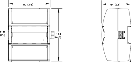
Dimensions including terminal base
|
90 W x 114 H x 64 D mm (3.6 W x 4.5 H x 2.5 D in.)
|
|
|
Weight including terminal base
|
0.275 kg (0.61 lb)
|
Weight excluding terminal base
|
0.152 kg (0.34 lb)
|
Terminal base
|
TB-IO-W1
|
| Universal inputs | |
|
|
Absolute maximum ratings
|
-0.5 to +24 VDC
|
A/D converter resolution
|
12 bits
|
| Digital | |
Range
|
Dry contact switch closure or open collector/open drain, 24 VDC, 2.4 mA
|
Minimum pulse width
|
120 ms
|
LED polarity
|
Software selectable, if the LED is activated when the input is high or low
|
LED color
|
Red or green, software selectable
|
| Counter | |
Range
|
Dry contact switch closure or open collector/open drain, 24 VDC, 2.4 mA
|
Minimum pulse width
|
20 ms
|
Maximum frequency
|
25 Hz
|
LED polarity
|
Software selectable, if the LED is activated when the input is high or low
|
LED color
|
Red or green, software selectable
|
| Supervised | |
5 V circuit, 1 or 2 resistors
|
|
Monitored switch combinations
|
Series only, parallel only, and series and parallel
|
Resistor range
|
1 to 10 kohm
|
| For a 2-resistor configuration, each resistor must have the same value +/- 5 % | |
| Voltage | |
Range
|
0 to 10 VDC
|
Accuracy
|
+/-(7 mV + 0.2 % of reading)
|
Resolution
|
2.7 mV
|
Impedance
|
100 kohm
|
Reliability check
|
Yes
|
| Current | |
Range
|
0 to 20 mA
|
Accuracy
|
+/-(0.03 mA + 0.4 % of reading)
|
Resolution
|
5.6 μA
|
Impedance
|
47 ohm
|
Reliability check
|
Yes
|
| Resistive | |
10 ohm to 10 kohm accuracy
|
+/-(7 + 4 x 10
-3
x R) ohm
|
| R = Resistance in ohm | |
10 kohm to 60 kohm accuracy
|
+/-(4 x 10
-3
x R + 7 x 10
-8
x R
2
) ohm
|
| R = Resistance in ohm | |
Reliability check
|
Yes
|
| Temperature | |
Range
|
-50 to +150 °C (-58 to +302 °F)
|
Reliability check
|
Yes
|
| Supported thermistors | |
Honeywell
|
20 kohm
|
Type I (Continuum)
|
10 kohm
|
Type II (I/NET)
|
10 kohm
|
Type III (Satchwell)
|
10 kohm
|
Type IV (FD)
|
10 kohm
|
Type V (FD w/ 11k shunt)
|
Linearized 10 kohm
|
Satchwell D?T
|
Linearized 10 kohm
|
Johnson Controls
|
2.2 kohm
|
Xenta
|
1.8 kohm
|
Balco
|
1 kohm
|
| Measurement accuracy | |
20 kohm, 10 kohm, 2.2 kohm, and 1.8 kohm
|
-50 to -30 °C: +/-1.5 °C (-58 to -22 °F: +/-2.7 °F)
|
-30 to 0 °C: +/-0.5 °C (-22 to +32 °F: +/-0.9 °F)
|
|
0 to 50 °C: +/-0.2 °C (32 to 122 °F: +/-0.4 °F)
|
|
50 to 100 °C: +/-0.5 °C (122 to 212 °F: +/-0.9 °F)
|
|
100 to 150 °C: +/-1.5 °C (212 to 302 °F: +/-2.7 °F)
|
|
Linearized 10 kohm
|
-50 to -30 °C: +/-3.0 °C (-58 to -22 °F: +/-5.4 °F)
|
-30 to 0 °C: +/-1.0 °C (-22 to +32 °F: +/-1.8 °F)
|
|
0 to 50 °C: +/-0.3 °C (32 to 122 °F: +/-0.5 °F)
|
|
50 to 100 °C: +/-0.5 °C (122 to 212 °F: +/-0.9 °F)
|
|
100 to 150 °C: +/-2.0 °C (212 to 302 °F: +/-3.6 °F)
|
|
1 kohm
|
-50 to +150 °C: +/-1.5 °C (-58 to +302° F: +/-2.7 °F)
|
| Analog outputs, AO | |
|
|
| Voltage | |
Range
|
0 to 10 VDC
|
Accuracy
|
+/-100 mV
|
Resolution
|
42 mV
|
Minimum load resistance
|
5 kohm
|
Load range
|
-1 to +2 mA
|
Reliability check
|
Yes
|
Central IO Modules
Mixed Modules
Important Information on Central IO Modules with Manufacturing Date Earlier Than 2021-W26