Concept
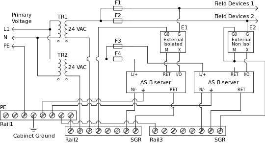
Grounding and Power for Systems with AS-B Servers
This section provides grounding and power recommendations for system configurations with AS-B servers.
Use the following recommendations to design a good working system:
It is preferable to have one signal ground rail long enough to cover all signal ground connections. If several ground rails are used, connect them in a tree configuration with wires of at least 4 mm 2 copper areas. This corresponds to AWG 12.
Connect the RET terminal number 4 or 5 from every AS-B server to the signal ground rail (SGR) using a 2.5 mm² (13 AWG) or larger wire.
Connect the root of the signal ground tree to cabinet ground and protective earth (PE).
Connect the signal output (Y-terminals) from external devices such as transmitters to the universal inputs.
For isolated devices, connect the signal common from the transmitter to the corresponding RET pin on the same AS-B server as the universal input. This recommendation applies to AS-B servers with 24 I/O points.
For non-isolated devices, connect the signal common from the transmitter to the SGR in the panel.
For AS-B servers with 36 I/O points, connect the signal common from the isolated or non-isolated transmitter to the SGR in the panel.
Connect the signal input (X-terminals) of external devices such as actuators to the analog outputs.
For isolated devices, connect the signal common from the actuator to the corresponding RET pin on the same AS-B server as the analog output. This recommendation applies to AS-B servers with 24 I/O points.
For non-isolated devices, connect the signal common from the actuator to the SGR in the panel.
For AS-B servers with 36 I/O points, connect the signal common from the isolated or non-isolated actuator to the SGR in the panel.
Connect the G0 (Power Ground/Common) of external devices, such as actuators and transmitters, to the SGR in the panel.
Connect thermistors to the universal input and corresponding RET terminal on the same AS-B server as the universal input. This recommendation applies to AS-B servers with 24 I/O points.
For AS-B servers with 36 I/O points, connect thermistors to the universal input and to the SGR in the panel.
One or several 24 V power transformers can be used to supply the system.
Connect different loads to different fuses in order to limit short circuit currents, but keep in mind that some of the signal ground wires will carry the sum of all load currents.
Use different fuses for connecting the current limited power source to the AS-B servers than for connecting the current limited power source to the field devices.
For UL listing compliance (Class 2 power), the fuses (circuit breakers) must be rated not more than 4A. For other regions that do not require UL compliance, fuses (circuit breakers) may be rated up to 6A.
For UL compliance, a UL Class 2 (100 VA or less) transformer may be used instead of the fuse/breaker limited transformer arrangement shown.

System configuration with AS-B servers
 I/O Wiring
 Grounding and Power
 AS-B Servers