Specifications
SpaceLogic IP-IO

Introduction
SpaceLogic™ IP-IO module provides I/O expansion to your HVAC application over BACnet/IP. The module can share its I/O resources across applications running in automation servers, BACnet/IP controllers, or third-party systems. With the support of local alarms and local trend logs, the IP-IO module avoids unnecessary traffic over the network while being able to log important information locally. The IP-IO module can be installed near facilities in the field, away from the automation server or the BACnet/IP controller. All IP-IO models support an optional display that provides insight and control of the inputs and outputs.
The IP-IO module has the following features:
IP enabled with dual-port Ethernet switch
Versatile onboard I/O point mix
Advanced monitoring
Commission mobile application for commissioning of the controller before the BMS is in place
Full EcoStruxure Building Operation software support, providing efficient engineering tools
For information on the maximum number of IP-IO modules that can be used with an automation server or a BACnet/IP controller, see the Architectural Guidelines.
IP connectivity and flexible network topologies
The IP-IO module is based on open protocols that simplify interoperability, IP configuration, and device management:
IP addressing
BACnet/IP communications
DHCP for easy network configuration
The IP-IO module has a dual-port Ethernet switch, which enables flexible network topologies:
Star
Daisy chain
Rapid Spanning Tree Protocol (RSTP) ring
In a star topology, the IP-IO module and the parent EcoStruxure BMS server are individually connected to an Ethernet switch. Daisy-chain multiple IP-IO modules together to reduce the installation time and cost. Use an RSTP ring topology when you want a non-operational IP-IO module to be detected and recovered quickly and efficiently.
Models with a versatile mix of I/O points
The IP-IO module comes in three models with different I/O point count and a versatile mix of I/O point types that match a wide variety of applications. The universal inputs/outputs are highly flexible and can be configured as either inputs or outputs.
|
I/O Point Types |
IP-IO-DI10 |
IP-IO-UIO10 |
IP-IO-UIO5DOFA4 |
|
Digital inputs |
10 |
- |
- |
|
Universal I/O Type Ub |
- |
10 |
5 |
|
Relay outputs Form A |
- |
- |
3 |
|
High power relay outputs Form A |
- |
- |
1 |
|
Configurations |
Digital Inputs |
Universal I/O Type Ub |
Relay Outputs Form A |
High Power Relay Outputs Form A |
|
Digital inputs |
yes |
yes |
- |
- |
|
Counter inputs |
yes |
yes |
- |
- |
|
Supervised inputs |
- |
yes |
- |
- |
|
Voltage inputs (0 to 10 VDC) |
- |
yes |
- |
- |
|
Current inputs (0 to 20 mA) |
- |
yes |
- |
- |
|
Temperature inputs |
- |
yes |
- |
- |
|
Resistive inputs |
- |
yes |
- |
- |
|
2-wire RTD temperature inputs |
- |
yes |
- |
- |
|
Voltage outputs (0 to 10 VDC) |
- |
yes |
- |
- |
|
Digital outputs |
- |
- |
yes |
yes |
|
Digital pulsed outputs |
- |
- |
yes |
yes |
|
PWM outputs |
- |
- |
yes |
yes |
|
Tristate outputs |
- |
- |
yes |
- |
|
Tristate pulsed outputs |
- |
- |
yes |
- |
The digital inputs can be used for cost effective sensing of multiple dry contact digital inputs in applications, such as equipment status monitoring or alarm point monitoring. As counter inputs, digital inputs are commonly used in energy metering applications.
The universal inputs/outputs are ideal for any mix of temperature, pressure, flow, status points, and similar point types in a building control system.
As counter inputs, the universal inputs/outputs are commonly used in energy metering applications. As RTD inputs, they are ideal for temperature points in a building control system. As supervised inputs, they are used for security applications where it is critical to know whether or not a wire has been cut or shorted. These events provide a separate indication of alarms and events in the system.
For all analog inputs, maximum and minimum levels can be defined to automatically detect over-range and under-range values.
The universal inputs/outputs can also be used as voltage outputs, without the need for external bias resistors. Therefore, the universal inputs/outputs support a wide range of devices, such as actuators.
The relay outputs support digital Form A point types. The Form A relays are designed for direct load applications.
The high power relay output is ideal for switching loads of up to 12 A, such as electrical heating elements.
Advanced monitoring
The I/O module supports local trends and alarms, enabling local operation when the I/O module is offline.
With user-defined fallback values, the I/O module outputs will be in a predictable state in cases of network disruption.
The battery-free power backup of the memory and real-time clock helps prevent data loss and allows seamless and quick recovery after a power disruption.
All IP-IO models can be equipped with a display add-on module (same module as used for the MP-C), which features an LCD display and five keys. With this module, you can manually override analog and digital outputs for testing, commissioning, and maintenance of equipment connected to the outputs. The display module's dedicated processing power ensures reliable override for maintenance applications. The override status can be viewed in EcoStruxure Building Operation WorkStation and WebStation, enabling precise monitoring and reliable control.

In WorkStation, you update the firmware of multiple I/O modules at the same time and with minimum down time. The EcoStruxure BMS server keeps track of the installed firmware to support backup, restore, and replacement of the I/O modules. The server can host I/O modules of different firmware versions.
Commission mobile application
The Commission mobile application is designed for local configuration, field deployment, and commissioning of IP-IO modules. The mobile application reduces the commissioning time, allows flexibility in project execution, and minimizes dependencies on network infrastructure.
The mobile application is designed for use with Android, Apple (iOS), and Microsoft Windows 10 and Windows 11 devices. For more information, see the EcoStruxure Building Commission Specification Sheet.

Using the Commission mobile application, you can connect to IP-IO modules and BACnet/IP controllers over the network. Using a wireless access point or a network switch, you can connect to a network of IP-IO modules and BACnet/IP controllers on the local IP network.
With the Commission mobile application, you can easily discover IP-IO modules and BACnet/IP controllers on the IP network. You can change the configuration of each module and controller, including the BACnet and IP network settings, location, and parent server. To save engineering time, you can save common device settings and then reuse them for devices of the same type and model.
The Commission mobile application does not require an EcoStruxure BMS server or a network infrastructure to be in place. You can use the mobile application to load the IP-IO application directly into the local IP-IO module and deploy the IP-IO module. The IP-IO application can be created offline using Project Configuration Tool or WorkStation while preserving all external bindings to server and controller applications using the IP-IO module's I/O points. You can also perform an I/O checkout to ensure that the IP-IO module's I/O points are configured, wired, and operating correctly.
Full EcoStruxure Building Operation software support
The power of the I/O module is fully realized when it is part of an EcoStruxure BMS, which provides the following benefits:
WorkStation/WebStation interface
Device discovery
Engineering efficiency
WorkStation and WebStation provide a consistent user experience regardless of which EcoStruxure BMS server the user is logged on to. The user can log on to the parent EcoStruxure BMS server to engineer, commission, supervise, and monitor the I/O modules and RP and MP controllers. For more information, see the WorkStation and WebStation specification sheets.
The enhanced Device Discovery in WorkStation enables you to easily identify the I/O modules on a BACnet network and to associate the I/O modules with their parent server.
The engineering and maintenance of the I/O modules can be done very efficiently using the EcoStruxure Building Operation reusability features. With these features, you can create library items (Custom Types) for a complete I/O module application that contains I/O point configurations and all necessary objects such as trends and alarms. The I/O module application in the Custom Types library is reusable across all I/O modules of the same model. You can use the I/O module application as a base for creating new I/O modules intended for similar applications. You can then edit the I/O module application, and the changes are automatically replicated to all I/O modules, while each I/O module keeps its local values.
WorkStation supports both online and offline engineering of the I/O modules. You can make the configuration changes online or use database mode to make the changes offline. In database mode, the changes are saved to the EcoStruxure Building Operation database so that you can apply the changes to the I/O modules later.
Project Configuration Tool enables you to perform all the engineering off site, without the need for physical hardware, which minimizes the time you need to spend on site. You can run the EcoStruxure BMS servers virtually and engineer the RP and MP controllers and the I/O modules before you deploy your server, controller, and I/O module applications to the servers, controllers, and I/O modules on site. For more information, see the Project Configuration Tool specification sheet.
In addition, you can use Automated Engineering Tool to facilitate your engineering process when using the I/O modules. This tool provides access to a library of standard I/O module applications that can be quickly configured and customized using the wizards and mass edit functions provided in the tool. You can then load these customized applications into your target server. The tool also enables the quick creation of your own templates based on the I/O module applications that you have developed. These templates facilitate a standard approach and easy reuse and duplication of common I/O module applications. For more information, see the Automated Engineering Tool specification sheet.

|
Product |
Part number |
|
IP-IO-DI10
|
SXWIPIOAA10001
|
|
IP-IO-UIO10
|
SXWIPIOBA10001
|
|
IP-IO-UIO5DOFA4
|
SXWIPIOCA10001
|
|
IP-IO-DI10-SMK a |
SXWIPIOAA1S001
|
|
IP-IO-UIO10-SMK a |
SXWIPIOBA1S001
|
|
IP-IO-UIO5DOFA4-SMK a |
SXWIPIOCA1S001
|
- Approved for use in UL 864 smoke control systems. The smoke control (SMK) models are shipped with a validated UL 864 software version, which can differ from the latest released software. For information on the approved software revisions for the device when used in UL 864 smoke control systems, see the Smoke Control System Approved Software Revisions - EcoStruxure Building Management document, 01-16001-XX-en.
|
Product |
Part number |
|
MP-C DISPLAY a (MP-C override display module) |
SXWMPCDSP10001
|
|
DIN-RAIL-CLIP, DIN-rail end clip
package of 25 pieces
|
SXWDINEND10001
|
- Approved for use in UL 864 smoke control systems.
For more information on part numbers for Network Connectivity Accessories, see the For more information, see Product Selection Guide - EcoStruxure Building ..
Specifications
| AC input | |||||||||||||
Nominal voltage
|
24 VAC
|
||||||||||||
Operating voltage range
|
+/- 20 %
|
||||||||||||
Frequency
|
50/60 Hz
|
||||||||||||
Maximum power consumption
|
17 VA
|
||||||||||||
Power input protection
|
MOV suppression and internal fuse
|
||||||||||||
| DC input | |||||||||||||
Nominal voltage
|
24 to 30 VDC
|
||||||||||||
Operating voltage range
|
21 to 33 VDC
|
||||||||||||
Maximum power consumption
|
9 W
|
||||||||||||
Power input protection
|
MOV suppression and internal fuse
|
||||||||||||
| Environment | |||||||||||||
Ambient temperature, operating
|
0 to 50 °C (32 to 122 °F) at normal operation
a
|
||||||||||||
-40 to +60 °C (-40 to +140 °F) for rooftop applications, horizontal installation only
a
|
|||||||||||||
| a) MP-C Display has an operating temperature range of -30 to +60 °C (-22 to +140 °F). | |||||||||||||
Ambient temperature, storage
|
-40 to +70 °C (-40 to +158 °F)
|
||||||||||||
Maximum humidity
|
95 % RH non-condensing
|
||||||||||||
| Material | |||||||||||||
Plastic flame rating
|
UL94-5V
|
||||||||||||
Ingress protection rating
|
IP 20
|
||||||||||||
| Mechanical | |||||||||||||
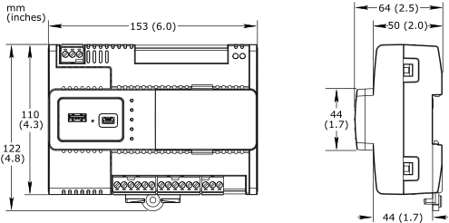
Dimensions
|
153 W x 110 H x 64 D mm (6.0 W x 4.3 H x 2.5 D in.)
|
||||||||||||
|
|||||||||||||
Weight, IP-IO-DI10
|
|||||||||||||
Including terminal blocks
|
0.337 kg (0.742 lb)
|
||||||||||||
Weight, IP-IO-UIO10
|
|||||||||||||
Including terminal blocks
|
0.336 kg (0.740 lb)
|
||||||||||||
Weight, IP-IO-UIO5DOFA4
|
|||||||||||||
Including terminal blocks
|
0.357 kg (0.787 lb)
|
||||||||||||
Recommended installation
|
DIN rail or flat surface in a cabinet
a
|
||||||||||||
| a) It is recommended to install the device in an enclosure (cabinet), unless local regulations allow an exception. | |||||||||||||
Terminal blocks
|
Removable
|
||||||||||||
| Compatibility | |||||||||||||
EcoStruxure BMS server communication
|
|||||||||||||
EcoStruxure Building Operation
|
version 2.0.4 and later
|
||||||||||||
EcoStruxure Building Management Smoke Control System
a
|
|||||||||||||
EcoStruxure Building Operation
|
For information, see the Smoke Control System Approved Software Revisions - EcoStruxure Building Management document, 01-16001-XX-en.
|
||||||||||||
| a) Applies to the Smoke Control (SMK) models. | |||||||||||||
| Agency compliances | |||||||||||||
Emission
|
RCM; BS/EN 61000-6-3; BS/EN IEC 63044-5-2; FCC Part 15, Sub-part B, Class B
|
||||||||||||
Immunity
|
BS/EN 61000-6-2; BS/EN IEC 63044-5-3
|
||||||||||||
Safety standards
|
BS/EN 60730-1; BS/EN 60730-2-11; BS/EN IEC 63044-3; UL 916 C-UL US Listed
|
||||||||||||
Smoke control product safety
a
|
UL 864
|
||||||||||||
| a) Applies to the Smoke Control (SMK) models and MP-C DISPLAY module. For specifications and information on the restrictions that apply to the SMK models and display module when used in UL 864 smoke control systems, see the EcoStruxure Building Management - Smoke Control System Design Guide, 04-16014-XX-en. | |||||||||||||
| Real-time clock | |||||||||||||
Accuracy, at 25 °C (77 °F)
|
+/-1 minute per month
|
||||||||||||
Backup time, at 25 °C (77 °F)
|
7 days minimum
|
||||||||||||
| Communication ports | |||||||||||||
Ethernet
|
Dual 10/100BASE-TX (RJ45)
|
||||||||||||
USB
|
1 USB 2.0 device port (mini-B)
|
||||||||||||
1 USB 2.0 host port (type-A), 5 VDC, 2.5 W
|
|||||||||||||
| Communications | |||||||||||||
BACnet
|
BACnet/IP, port configurable, default 47808
|
||||||||||||
BTL B-ASC (BACnet Application Specific Controller)
a
|
|||||||||||||
| a) See the BTL Product Catalog for up-to-date details on BTL listed firmware revisions on BACnet International's home page. | |||||||||||||
| CPU | |||||||||||||
Frequency
|
500 MHz
|
||||||||||||
Type
|
ARM Cortex-A7 dual-core
|
||||||||||||
DDR3 SDRAM
|
128 MB
|
||||||||||||
NOR flash memory
|
32 MB
|
||||||||||||
Memory backup
|
128 kB, FRAM, non-volatile
|
||||||||||||
| MP-C Display (Optional) | |||||||||||||
Removable
|
No
|
||||||||||||
Display size
|
36 W x 17 H mm (1.4 W x 0.7 H in.)
|
||||||||||||
Display resolution
|
128 x 64 pixels
|
||||||||||||
Display type
|
FSTN monochrome LCD, white color transflective backlight
|
||||||||||||
Power consumption
|
max. 0.15 W (45 mA at 3.3 V)
|
||||||||||||
Ambient temperature, operating
|
-30 to +60 °C (-22 to +140 °F)
|
||||||||||||
Ambient temperature, storage
|
-40 to +70 °C (-40 to +158 °F)
|
||||||||||||
Maximum humidity
|
95 % RH non-condensing
|
||||||||||||
Weight
|
0.035 kg (0.077 lb)
|
||||||||||||
Compliance with standards
|
EN ISO 16484-2
|
||||||||||||
| Digital inputs, DI | |||||||||||||
Channels, IP-IO-DI10
|
10, DI1 to DI10
|
||||||||||||
Channels, IP-IO-UIO10
|
0
|
||||||||||||
Channels, IP-IO-UIO5DOFA4
|
0
|
||||||||||||
Absolute maximum ratings
|
-0.5 to +24 VDC
|
||||||||||||
Digital input protection
|
Transient voltage suppressor on each digital input
|
||||||||||||
| Digital inputs | |||||||||||||
Range
|
Dry contact switch closure or open collector/open drain, 24 VDC, typical wetting current 2.4 mA
|
||||||||||||
Minimum pulse width
|
150 ms
|
||||||||||||
| Counter inputs | |||||||||||||
Range
|
Dry contact switch closure or open collector/open drain, 24 VDC, typical wetting current 2.4 mA
|
||||||||||||
Minimum pulse width
|
20 ms
|
||||||||||||
Maximum frequency
|
25 Hz
|
||||||||||||
| Universal inputs/outputs, Ub | |||||||||||||
Channels, IP-IO-DI10
|
0
|
||||||||||||
Channels, IP-IO-UIO10
|
10 Ub, Ub1 to Ub10
|
||||||||||||
Channels, IP-IO-UIO5DOFA4
|
5 Ub, Ub1 to Ub5
|
||||||||||||
Absolute maximum ratings
|
-0.5 to +24 VDC
|
||||||||||||
A/D converter resolution
|
16 bits
|
||||||||||||
Universal input/output protection
|
Transient voltage suppressor on each universal input/output
|
||||||||||||
| Digital inputs | |||||||||||||
Range
|
Dry contact switch closure or open collector/open drain, 24 VDC, typical wetting current 2.4 mA
|
||||||||||||
Minimum pulse width
|
150 ms
|
||||||||||||
| Counter inputs | |||||||||||||
Range
|
Dry contact switch closure or open collector/open drain, 24 VDC, typical wetting current 2.4 mA
|
||||||||||||
Minimum pulse width
|
20 ms
|
||||||||||||
Maximum frequency
|
25 Hz
|
||||||||||||
| Supervised inputs | |||||||||||||
5 V circuit, 1 or 2 resistors
|
|||||||||||||
Monitored switch combinations
|
Series only, parallel only, and series and parallel
|
||||||||||||
Resistor range
|
1 to 10 kohm
|
||||||||||||
| For a 2-resistor configuration, each resistor must have the same value +/- 5 % | |||||||||||||
| Voltage inputs | |||||||||||||
Range
|
0 to 10 VDC
|
||||||||||||
Accuracy
|
+/-(7 mV + 0.2 % of reading)
|
||||||||||||
Resolution
|
1.0 mV
|
||||||||||||
Impedance
|
100 kohm
|
||||||||||||
| Current inputs | |||||||||||||
Range
|
0 to 20 mA
|
||||||||||||
Accuracy
|
+/-(0.01 mA + 0.4 % of reading)
|
||||||||||||
Resolution
|
1 μA
|
||||||||||||
Impedance
|
47 ohm
|
||||||||||||
| Resistive inputs | |||||||||||||
10 ohm to 10 kohm accuracy
|
+/-(7 + 4 x 10
-3
x R) ohm
|
||||||||||||
| R = Resistance in ohm | |||||||||||||
10 kohm to 60 kohm accuracy
|
+/-(4 x 10
-3
x R + 7 x 10
-8
x R
2
) ohm
|
||||||||||||
| R = Resistance in ohm | |||||||||||||
| Temperature inputs (thermistors) | |||||||||||||
Range
|
-50 to +150 °C (-58 to +302 °F)
|
||||||||||||
| Supported thermistors | |||||||||||||
Honeywell
|
20 kohm
|
||||||||||||
Type I (Continuum)
|
10 kohm
|
||||||||||||
Type II (I/NET)
|
10 kohm
|
||||||||||||
Type III (Satchwell)
|
10 kohm
|
||||||||||||
Type IV (FD)
|
10 kohm
|
||||||||||||
Type V (FD w/ 11k shunt)
|
Linearized 10 kohm
|
||||||||||||
Satchwell D?T
|
Linearized 10 kohm
|
||||||||||||
Johnson Controls
|
2.2 kohm
|
||||||||||||
Xenta
|
1.8 kohm
|
||||||||||||
Balco
|
1 kohm
|
||||||||||||
| Measurement accuracy | |||||||||||||
20 kohm
|
-50 to -30 °C: +/-1.5 °C (-58 to -22 °F: +/-2.7 °F)
|
||||||||||||
-30 to 0 °C: +/-0.5 °C (-22 to +32 °F: +/-0.9 °F)
|
|||||||||||||
0 to 100 °C: +/-0.2 °C (32 to 212 °F: +/-0.4 °F)
|
|||||||||||||
100 to 150 °C: +/-0.5 °C (212 to 302 °F: +/-0.9 °F)
|
|||||||||||||
10 kohm, 2.2 kohm, and 1.8 kohm
|
-50 to -30 °C: +/-0.75 °C (-58 to -22 °F: +/-1.35 °F)
|
||||||||||||
-30 to +100 °C: +/-0.2 °C (-22 to +212 °F: +/-0.4 °F)
|
|||||||||||||
100 to 150 °C: +/-0.5 °C (212 to 302 °F: +/-0.9 °F)
|
|||||||||||||
Linearized 10 kohm
|
-50 to -30 °C: +/-2.0 °C (-58 to -22 °F: +/-3.6 °F)
|
||||||||||||
-30 to 0 °C: +/-0.75 °C (-22 to +32 °F: +/-1.35 °F)
|
|||||||||||||
0 to 100 °C: +/-0.2 °C (32 to 212 °F: +/-0.4 °F)
|
|||||||||||||
100 to 150 °C: +/-0.5 °C (212 to 302 °F: +/-0.9 °F)
|
|||||||||||||
1 kohm
|
-50 to +150 °C: +/-1.0 °C (-58 to +302° F: +/-1.8 °F)
|
||||||||||||
| RTD temperature inputs | |||||||||||||
Supported RTDs
|
Pt1000, Ni1000, and LG-Ni1000
|
||||||||||||
| Pt1000 | |||||||||||||
Sensor range
|
-50 to +150 °C (-58 to +302 °F)
|
||||||||||||
|
|||||||||||||
| Ni1000 | |||||||||||||
Sensor range
|
-50 to +150 °C (-58 to +302 °F)
|
||||||||||||
|
|||||||||||||
| LG-Ni1000 | |||||||||||||
Sensor range
|
-50 to +150 °C (-58 to +302 °F)
|
||||||||||||
|
|||||||||||||
| RTD temperature wiring | |||||||||||||
Maximum wire resistance
|
20 ohm/wire (40 ohm total)
|
||||||||||||
Maximum wire capacitance
|
60 nF
|
||||||||||||
| The wire resistance and capacitance typically corresponds to a 200 m wire. | |||||||||||||
| Voltage outputs | |||||||||||||
Range
|
0 to 10 VDC
|
||||||||||||
Accuracy
|
+/-60 mV
|
||||||||||||
Resolution
|
10 mV
|
||||||||||||
Minimum load resistance
|
5 kohm
|
||||||||||||
Load range
|
-1 to +2 mA
|
||||||||||||
| Relay outputs, DO | |||||||||||||
Channels, IP-IO-DI10
|
0
|
||||||||||||
Channels, IP-IO-UIO10
|
0
|
||||||||||||
Channels, IP-IO-UIO5DOFA4
|
3, DO1 to DO3
|
||||||||||||
Contact rating
|
250 VAC/30 VDC, 2 A, Pilot Duty (C300)
|
||||||||||||
Switch type
|
Form A Relay
|
||||||||||||
Single Pole Single Throw
|
|||||||||||||
Normally Open
|
|||||||||||||
Isolation contact to system ground
|
3000 VAC
|
||||||||||||
Cycle life (Resistive load)
|
At least 100,000 cycles
|
||||||||||||
Minimum pulse width
|
100 ms
|
||||||||||||
| High power relay outputs, DO | |||||||||||||
Channels, IP-IO-DI10
|
0
|
||||||||||||
Channels, IP-IO-UIO10
|
0
|
||||||||||||
Channels, IP-IO-UIO5DOFA4
|
1, DO4
|
||||||||||||
Contact rating
|
250 VAC/24 VDC, 12 A, Pilot Duty (B300)
|
||||||||||||
Switch type
|
Form A Relay
|
||||||||||||
Single Pole Single Throw
|
|||||||||||||
Normally Open
|
|||||||||||||
Isolation contact to system ground
|
5000 VAC
|
||||||||||||
Cycle life (Resistive load)
|
At least 100,000 cycles
|
||||||||||||
Minimum pulse width
|
100 ms
|
||||||||||||
Terminals
Follow proper installation wiring diagrams and instructions, including these instructions:
All IP-IO models have several RET terminals for connection of I/O returns, so a common chassis/signal ground rail is optional and may not be needed.
Individual 24 V power sources to the field must be current limited to maximum 4 A for UL compliant installations, and maximum 6 A in other areas.
For more information on wiring, see Hardware Reference Guide.


