
How to
Installing an IP-IO Module on a Flat Surface
You install an IP-IO module on a flat surface inside a cabinet to ensure that the device is securely fastened and to allow for sufficient ventilation.
The IP-IO module device can be installed on a DIN rail or other flat surface inside a cabinet.
A DIN rail is a common and convenient technique for installing the IP-IO module along with other associated control and monitoring devices. The most efficient ventilation is achieved with the wall-mounted DIN rail oriented horizontally and with adequate space provided between the IP-IO module rail and adjacent rails or other panel-mounted devices.
The IP-IO module is typically installed horizontally (on a DIN rail going from left to right), with the device label text in the upright position reading left to right.

IP-IO module installed on a horizontal DIN rail
The restrictions on installing the device in other orientations differ depending on the operating conditions.
Under normal operating conditions of 0 to 50 °C (32 to 122 °F), the IP-IO module can be installed in the following orientations:
Horizontally (on a DIN rail going from left to right), with the device label text in the upright position reading left to right. See “a” in the following figure.
Vertically (on a DIN rail going from top to bottom), which means that the device is rotated +90 degrees or -90 degrees from the horizontal position. See “b” and “c” in the following figure.
Installing the IP-IO module rotated 180 degrees from the horizontal position with device label text up and down (“e” in the figure), face down from a ceiling (“d” in the figure), or face up on a horizontal surface (“f” in the figure) is not supported.
")
Installation orientation restrictions for the IP-IO module operated in normal conditions, 0 to 50 °C (32 to 122 °F)
When the IP-IO module is used for rooftop applications, -40 to +60 °C (-40 to +140 °F), the device should be installed horizontally, with the device label text in the upright position reading left to right. See “a” in the following figure. Any other installation orientation (“b”, “c”, “d”, “e”, and “f” in the figure) may exceed the IP-IO module's thermal specifications, which can damage the module.
")
Installation orientation restrictions for the IP-IO module operated at -40 to +60 °C (-40 to +140 °F)
The IP-IO module can be installed in a standard DIN enclosure.
When installing IP-IO modules in a cabinet, it is recommended to provide ample space between the DIN rails and modules for sufficient ventilation.

IP-IO modules installed on horizontal DIN rails in a cabinet
To help prevent the device from sliding down or sideways on the DIN rail, install an end clip for DIN 35 (part number SXWDINEND10001) tightly against the bottom or rightmost device on the rail. The end clip is easily removed if you bend the snap lock open with a screwdriver.

End clip for DIN 35 fixed across the DIN rail
The IP-IO module is delivered with terminal blocks installed on the device.
The terminal blocks are removable. You can replace an IP-IO module in seconds because no terminal wiring is affected. The only exception is the high power relay output on the IP-IO-UIO5DOFA4 model, which uses a two-position fixed terminal block due to current requirements.
All IP-IO module models can be equipped with MP-C Display (part number SXWMPCDSP10001), which is an add-on module that enables manual override control of analog and digital outputs. The module consists of an LCD display and keys. The module is designed for permanent installation.

MP-C Display installed on an IP-IO module
Do not try to remove the MP-C Display module as it may damage the enclosure and the module. Once installed, the MP-C Display module cannot be removed.
Refer to the dimensional drawing before installing the IP-IO module.
action_zoom_plus_stroke 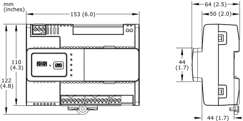
Ensure that you have the proper mounting hardware and anchoring system.
Check the weight-bearing load before choosing your mounting hardware.
Find a suitable location and surface on which to mount the IP-IO module.
Drill three mounting holes that fit number 8 or M4 screws (or anchors):
Two holes for the top two screws on which you hang the IP-IO module
One hole for the screw at the bottom that prevents the device from being lifted off the top two screws
Use the following drawing to measure out the location of the three holes for the IP-IO module.
action_zoom_plus_stroke 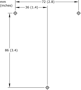 Note:
Note:You can also use the 1:1 drill template in the installation sheet that comes with each IP-IO module.
Install number 8 or M4 (4 mm) pan head self-tapping screws (or anchors) in the two top holes, leaving approximately 5 mm (0.2 inch) space between the head of the screw (or anchor) and the flat surface to accommodate the IP-IO module material thickness.
action_zoom_plus_stroke 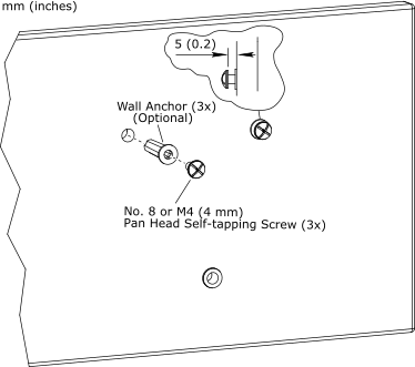
Fit the two keyhole slots on the back of the IP-IO module enclosure to the heads of the mounted screws (or anchors) and then slide the IP-IO module down in place on the screws (or anchors).
action_zoom_plus_stroke 
Fit the bottom screw (or anchor) to the hole at the bottom of the IP-IO module and tighten the screw (or anchor).
action_zoom_plus_stroke 
 IP-IO Module Device Installation
Installing an IP-IO Module on a DIN Rail
Installing MP-C Display
Installing a Terminal Block on an IP-IO Module
Removing a Terminal Block from an IP-IO Module
IP-IO Module Device Installation
Installing an IP-IO Module on a DIN Rail
Installing MP-C Display
Installing a Terminal Block on an IP-IO Module
Removing a Terminal Block from an IP-IO Module