
How to
Plugging an External Connector into an RP Controller Expansion Module
You plug an external connector into an RP controller expansion module to connect lights, blinds, dry contact digital inputs, or AC power to the module.
The RP controller expansion modules have PCB mounted connectors for the power input, outputs, and digital inputs. The PCB mounted connectors mate with pluggable connectors:
The light modules, blind modules, and the RP-C-EXT-REL-4 relay module have mechanically keyed and color-coded connectors, which allows the matching external connectors to be plugged in on site quickly and easily.
The CRS-HH-REL-10 relay module has PCB header connectors for pluggable screw terminal blocks, which are easy to install and remove from the device.
Light Modules, Blind Modules, and RP-C-EXT-REL-4 Relay Module
The pluggable connectors mean time savings and cost reductions for the installation, compared to wiring terminal blocks on site. The connectors can quickly and easily be plugged together on site.
The RP controller expansion modules use 2, 3, 4 or 5 pole connectors for the different inputs and outputs. The 4-pole connector has a 5-pole frame.
The connectors are mechanically keyed, which means the following connections cannot be made:
A connector for AC mains and high-voltage applications cannot be plugged into a connector for low-voltage applications.
A connector for low-voltage applications cannot be plugged into a connector for AC mains and high-voltage applications.
The matching connectors are locked together.
The connectors are also color-coded to help the installers and electricians to choose the correct, matching external connector. The connectors are color-coded:
Black: For AC mains power applications such as power supply input, blind high-voltage outputs, SMI (HV) blind outputs, and relay outputs.
Pastel blue: For dimming applications such as DALI inputs/outputs and 0-10V light outputs with power distribution.
Light blue: For low-voltage applications such as blind low-voltage outputs (24 VDC), 0-10V light outputs without power distribution, SMI LoVo (LV) blind outputs, and digital inputs (5 VDC).
")
Color-coded connectors (example)
The matching external connectors are not provided but need to be ordered separately from Schneider Electric. For more information, see Required External Connectors for the RP Controller Expansion Modules .
CRS-HH-REL-10 Relay Module
The CRS-HH-REL-10 relay module uses pluggable screw terminal blocks, which are easy to install and remove from the device.
The terminal blocks are delivered in a plastic bag with the device.
The terminal blocks are used as follows:
2-pole terminal blocks (x10) for the relay outputs
9-pole terminal blocks (x2) for the digital inputs
|
Terminal Block Connector |
Recommended Torque |
|
2-pole |
0.5 Nm (4.4 lbf.in) |
|
9-pole |
0.2 Nm (1.7 lbf.in) |

Pluggable screw terminal blocks installed on the CRS-HH-REL-10 relay module
Ensure that you use the correct external connector, with a keying that matches the keying of the mating connector on the module and with the same color as the mating connector.
For more information, see Required External Connectors for the RP Controller Expansion Modules .
Align the connector locking latch (or tab) of the external connector with the locking tab (or latch) of the mating connector.
Push the external connector into the mating connector until the connector locking latch and locking tab engage (there will be an audible click sound).
action_zoom_plus_stroke 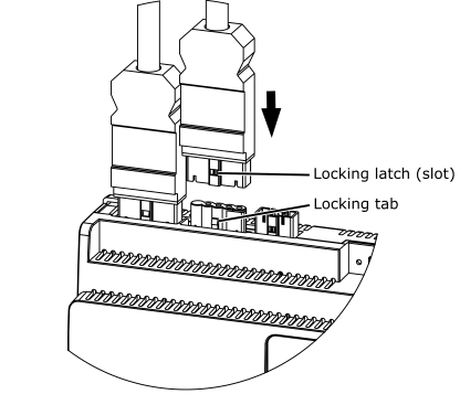
 RP Controller Expansion Module Pluggable Connectors
Required External Connectors for the RP Controller Expansion Modules
RP Controller Expansion Module Device Installation
Removing an External Connector from an RP Controller Expansion Module
RP Controller Expansion Module Pluggable Connectors
Required External Connectors for the RP Controller Expansion Modules
RP Controller Expansion Module Device Installation
Removing an External Connector from an RP Controller Expansion Module