
Concept
Operator Display Communication Ports
Operator Display provides the following combination of communication ports:
Two Ethernet ports
Two USB ports
One RS-232C port
One RS-485 port
 Warning
|
Side |
Identification |
|
Bottom
|
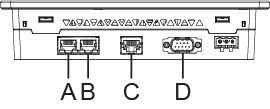
A: Ethernet interface (ETH2) – Inactive B: Ethernet interface (ETH1) C: Serial interface (RJ-45, RS-485) (COM2) – Inactive D: Serial interface (RS-232C) (COM1) – Inactive |
|
Rear
|
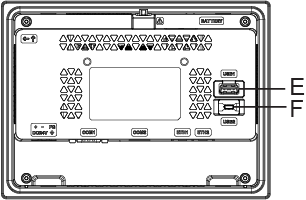
E: USB (Type A) interface (USB1) F: USB (micro-B) interface (USB2) |
Ethernet Ports
The two Ethernet ports are labelled:
ETH1
ETH2
The two Ethernet ports are 10/100BASE-TX (RJ45) ports. They are used to connect Operator Display to the BACnet/IP network. ETH1 is the only port used; ETH2 is inactive.
Use only the SELV (Safety Extra-Low Voltage) circuit to connect the Ethernet ports.
For more information, see Communication Port Wiring .
USB Ports
The two USB ports are of different types:
USB host port (labelled USB-1)
USB device port (labelled USB-2)
The USB host port is a USB 2.0 type-A port, which is rated 2.5 W. This port is used to transfer data to and from Operator Display using a USB stick (FAT formatted).
The USB device port is a USB 2.0 mini-B port. This port is used as a temporary connection only during maintenance and setup of the device.
Use only the SELV (Safety Extra-Low Voltage) circuit to connect the USB ports.
For more information, see Communication Port Wiring .
RS-232C Port
The RS-232C port is a D-Sub 9-pin plug connector, and labelled as COM1. This port is inactive on Operator Display.
RS-485 Port
The RS-485 port is an RJ45 port (modular jack), and labelled as COM2. This port is inactive on Operator Display.
Hardware Overview
Operator Display
Communication Port Wiring