
How to
Replacing the Battery on Operator Display
You replace the battery to help ensure the data backup of the Operator Display memory and internal clock is not lost.
Operator Display is panel-mounted in equipment rooms using installation fasteners.
Operator Display is designed for use on flat surfaces of IP 65F, Type 1, Type 4X (indoor use only) and Type 13 enclosures.
Be aware of the following when building Operator Display into an end-user product:
The rear of Operator Display is not approved as an enclosure.
When building Operator Display into an end-user product, use an enclosure that satisfies standards as the end-user product’s overall enclosure.
Install Operator Display in an enclosure with mechanical rigidity.
Operator Display is not designed for outdoor use. UL certification obtained is for indoor use only.
Install and operate Operator Display with its front facing outward.
The necessary torque is 0.5 Nm (4.4 lbf.in).
IP 65F is not part of the UL certification.
Installation Requirements
Read the specific security hardening recommendations before installing Operator Display. For more information, see Operator Display Hardening .
 Caution
Before installing Operator Display, read the following list of installation requirements:
Check that the installation wall or cabinet surface is flat, in good condition and has no jagged edges. Metal reinforcing strips may be attached to the inside of the wall, near the panel-cut, to increase its rigidity.
Decide on the thickness of the enclosure wall, based on the level of strength required. Even if the installation wall thickness is within the recommended range for the panel cut dimensions, depending on wall’s material, size, and installation location of Operator Display and other devices, the installation wall could warp. To help prevent warping, the installation surface may need to be strengthened.
Check that the ambient air temperature and the ambient humidity are within their specified ranges in environmental specifications. When installing Operator Display in a cabinet or enclosure, the ambient air temperature is the cabinet’s or enclosure’s internal temperature. For more information, see Operator Display .
action_zoom_plus_stroke 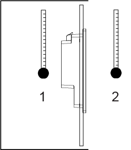
1. Internal temperature
2. External temperature
Ensure that heat from surrounding equipment does not cause this product to exceed its standard operating temperature.
When installing this product in a slanted position, the product front should not be inclined by more than 30 degrees.
action_zoom_plus_stroke 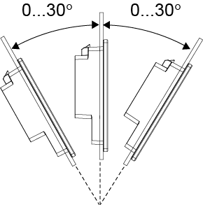
For easier maintenance, operation and improved ventilation, install this product at least 100 mm (3.94 in) away from adjacent structures and other equipment as shown in the following illustration:
action_zoom_plus_stroke 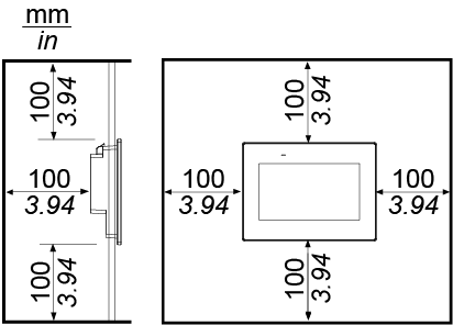
When applying and installing this product, it is important that steps are taken to help eliminate any pressure difference between the inside and the outside of the enclosure in which this product is mounted. Higher pressure inside the enclosure can cause delamination of the front membrane of the display. Even a small pressure difference inside the enclosure will act on the large area of the membrane and can result in sufficient force to delaminate the membrane and thus cause the failure of the touch capability. Pressure differences can often occur in applications where there are multiple fans and ventilators moving air at different rates in different rooms. Follow these techniques to help ensure that this product's function is not affected by this misapplication:
Seal all conduit connections inside of the enclosure, especially those that lead to other rooms that may be at a different pressure.
Where applicable, install a small weep hole at the bottom of the enclosure to allow equalization of the internal and external pressure.
Specific measurements must be taken into consideration when preparing to install Operator Display on a panel.

Panel cut dimensions
|
A |
B |
C |
|
190 mm (+1/0 mm) (7.48 in [+0.04/0 in]) |
135 mm (+1/0 mm) (5.31 in [+0.04/0 in]) |
1.6 to 5 mm (0.06 to 0.2 in) |
 Danger
Disconnect the power supply from this product.
Touch the housing or ground connection to discharge any electrostatic charge from your body.
Place this product on a flat, level surface, with the front side pointing up.
Open the battery slot on the top of this product.
action_zoom_plus_stroke 
action_zoom_plus_stroke 
1. Battery slot
2. Safety alert symbol (see the safety messages stated above)
Remove the spent battery from the tray by touching the battery from the bottom.
action_zoom_plus_stroke 
Put the new battery (CR2032) on the tray in accordance with the polarity markings in the tray and on the battery.
Insert the tray into the battery slot.
Reconnect the power supply to this product.
Configure the date and time. For more information, see Configuring Date and Time .
Removing Operator Display
 Operator Display Installation
Configuring Date and Time
Operator Display
Installing Operator Display on a Panel
Operator Display Installation
Configuring Date and Time
Operator Display
Installing Operator Display on a Panel