
Concept
Grounding and Power for Systems with Operator Display
This section provides grounding and power recommendations for system configurations with Operator Display, which supports 24 VDC input power.
 Warning
The SG (signal ground) and FG (functional ground) terminals are separated inside this product.
When the FG terminal is connected, ensure the wire is grounded. Not grounding this product can result in excessive electromagnetic interference (EMI).
DC Power Cord Preparation
Make sure the ground wire is either the same or heavier gauge than the power wires.
Do not use aluminum wires in the power supply's power cord.
If the ends of the individual wires are not twisted correctly, the wires may create a short circuit.
The conductor type is solid or stranded wire.
Use copper wire rated for 75 °C (167 °F) or higher.
Use the SELV (Safety Extra-Low Voltage) circuit and LIM (Limited Energy) circuit for DC input.
|
Item |
Specification |
|
Power cord diameter |
0.75 to 2.5 mm 2 (18 to 13 AWG) a |
|
Conductor type |
Solid or stranded wire |
|
Conductor length |
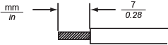
|
|
Recommended driver |
Flat-head screwdriver, size 0.6 x 3.5 mm (0.02 x 0.14 in) |
a) For UL compatibility, use AWG 14 or AWG 13.
|
|
Connection |
Wire |
|
|
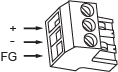
+ |
24 Vdc |
|
- |
0 Vdc |
|
|
FG |
Grounded terminal. Connect the FG terminal properly to the ground. |
 Danger
This product’s power supply cord should not be bundled with or kept close to main circuit lines(high voltage, high current), power lines, or input/output lines, and their various systems should be kept separate. When power lines cannot be wired via a separate system, use shielded cables for input/output lines.
Make the power cord as short as possible, and twist the ends of the wires together (i.e. twisted-pair cabling) from close to the power supply unit.
If there is an excess amount of noise on the power supply line, reduce the noise with a noise filter before turning on the power.
Connect a surge protection device to handle power surges.
To increase noise resistance, attach a ferrite core to the power cable.
When supplying power to this product, connect the power as shown below.
action_zoom_plus_stroke 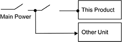
Use the SELV (Safety Extra-Low Voltage) circuit and LIM (Limited Energy) circuit for DC input.
The following shows a surge protection device connection:
action_zoom_plus_stroke 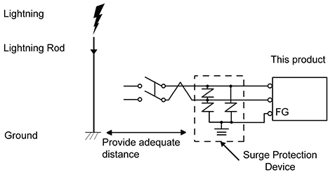
Attach a surge protection device to help prevent damage to this product as a result of a lightning-induced power surge from a large electromagnetic field generated from a direct lightning strike. We also strongly recommend connecting the crossover grounding wire of this product to a position close to the ground terminal of the surge protection device. It is expected that there will be an effect on this product due to fluctuations in grounding potential when there is a large surge flow of electrical energy to the lightning rod ground at the time of a lightning strike. Provide adequate distance between the lightning rod grounding point and the surge protection device grounding point.
If the voltage variation is outside the prescribed range, connect a regulated power supply.
action_zoom_plus_stroke 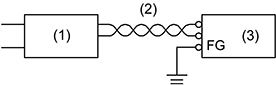
1 Regulated power supply
2 Twisted-pair cord
3 This product
Always ground the FG (functional ground) terminal. Separate this product from the FG of other devices as shown below.
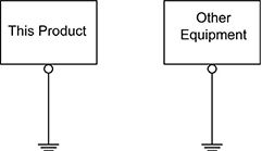
Check that the grounding resistance is 100 ohms or less. a
The FG wire should have a cross-sectional area greater than 2 mm 2 (AWG14). a Create the connection point as close to this product as possible and make the wire as short as possible.
When using a long grounding wire, replace the thin wire with a thicker wire, and place it in a duct.
When connecting the FG (functional ground) and the SG (signal ground), ensure that no ground loop is formed.
a) Observe local codes and standards.
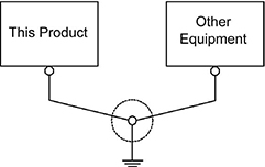
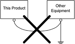
Electromagnetic Interference (EMI) can be created if devices are improperly grounded. EMI cancause loss of communication. If exclusive grounding is not possible, use a common grounding point as shown in the configuration below. Do not use any other configuration for common grounding.
Correct grounding
Incorrect grounding
 I/O Wiring
Grounding and Power
Operator Display
I/O Wiring
Grounding and Power
Operator Display