
How to
Printing a Wiring List for the I/O Bus
You print an I/O wiring list for the I/O bus that describes which I/O points are associated with each I/O module. You use the printed copy of this list to help wire the I/O bus network.
If a Module ID is Null, you cannot print the wiring list. If a channel is Null, the I/O point labels do not display in the wiring list.
The I/O bus consists of the following parts:
Power bus
Address bus
Communication bus

I/O bus parts
The power bus distributes 24 VDC power from the power supply to the SmartStruxure server device and the I/O modules. The SmartStruxure server device can be either an AS-P or an Automation Server.
Use the power budget to calculate the maximum number of devices that the power supply can supply. If more devices are used, additional power supplies must be added to the I/O bus.
For more information, see Power Budget .
The address bus is used to pass the address from the terminal base backplane to the electronics module that is installed on the terminal base to the next terminal base on the I/O bus. Typically, the physical position (address) of the devices on the I/O bus should match the module IDs in Building Operation. For more information, see Device Addressing .
|
Electronics Module |
Physical Position Number |
Building Operation Module ID |
|
Power Supply |
1 |
Number is hidden in WorkStation |
|
AS-P or Automation Server |
2 |
Number is hidden in WorkStation |
|
I/O module |
3 |
3 |
|
I/O module |
n |
n <=32 |
The communication bus enables serial (RS-485) communication between the SmartStruxure server device and the I/O modules. The SmartStruxure server device can be either an AS-P or an Automation Server. The SmartStruxure server device controls and supervises the communication on the communication bus. The I/O modules also monitor their communication status. When a new I/O module is configured and connected to the I/O bus, the SmartStruxure server device automatically detects the new I/O module.
All the buses use a common ground, which is connected to the signal return paths with terminals called "RET". The signal return path is also called signal ground.
In WorkStation, in the System Tree pane, click the IO Bus on a SmartStruxure server device.
On the Actions menu, click Print IO wiring list .
action_zoom_plus_stroke 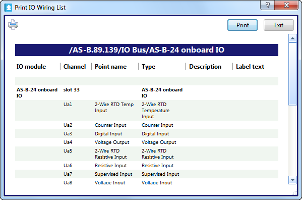
In the Print IO Wiring List dialog box, click the Printer icon
.action_zoom_plus_stroke 
To print a wiring list for a single I/O module, right-click the selected I/O module.
Click Print IO wiring list .
action_zoom_plus_stroke 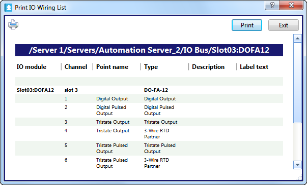
Click the Printer icon
.action_zoom_plus_stroke
Observe that the complete path to the I/O module is displayed on the title bar for the I/O wiring list.
 I/O Bus Parts
I/O Bus Restrictions
I/O Bus Parts
I/O Bus Restrictions
 I/O Modules in the Work Area