
Concept
RTD-DI-16 Central IO Module
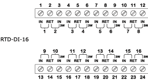
The RTD-DI-16 module is an RTD temperature, RTD resistance, digital, counter, or resistance input, 16-channel I/O module. Each channel has a dedicated two-color (red and green) status LED.
You can configure the channel status LED to display either red or green for each input state. The front panel contains both the I/O channel and module status LEDs.

RTD-DI-16 Central IO Module
Inputs
The inputs of the RTD-DI-16 Central IO module are designed to read seven different types of inputs:
2-wire RTD temperature
3-wire RTD temperature
2-wire RTD resistive
3-wire RTD resistive
Digital
Counter
Resistive

Internal configuration
Applied voltages beyond the absolute maximum ratings cause over current in the protection component D Z .
In a 2-wire configuration, the leads are connected to IN and RET or RET and IN/3W. This provides up to 16 inputs for 2-wire configurations.
In a 3-wire configuration, the leads are connected to IN, RET, and IN/3W. This provides up to 8 inputs for 3-wire configurations.
The I/O bus in the terminal base provides the Central IO module with power and an address.
The address value in the I/O bus is increased by one for each terminal base. The I/O bus also enables RS-485 communication between the Central IO module and the automation server.
The external connection of a 2-wire RTD temperature input is shown in the following figure.

2-wire temperature input external connection
R T is the monitored external RTD.
R W is the wiring resistance.
In the internal configuration of the RTD temperature input, I S is used according to the following table.
|
RTD type |
I S |
|
Pt100 |
1.5 mA |
|
Pt1000 |
750 µA |
|
Ni1000 |
750 µA |
|
LG-Ni1000 |
750 µA |
|
JCI-Ni1000 |
750 µA |
The current source nominal duty cycle is 5 %. The current to the RTD is pulsed to minimize self-heating.
When an input is used as a 2-wire RTD temperature input, you need to specify the wiring resistance in the software.
The input is measuring the total resulting voltage and the voltage across the RTD is calculated. The voltage across the RTD is then converted to a raw resistance value.
The external connection of a 3-wire RTD temperature input is shown in the following figure.

3-wire temperature input external connection
R T is the monitored external RTD.
R W is the wiring resistance.
In the internal configuration of the RTD temperature input, I S is used according to the following table.
|
RTD type |
I S |
|
Pt100 |
1.5 mA |
|
Pt1000 |
750 µA |
|
Ni1000 |
750 µA |
|
LG-Ni1000 |
750 µA |
|
JCI-Ni1000 |
750 µA |
The current source nominal duty cycle is 5 %. The current to the RTD is pulsed to minimize self-heating.
When an input is used as a 3-wire RTD temperature input, the Central IO module automatically compensates for the wiring resistance using the third wire.
The input is measuring the total resulting voltage and the voltage across the RTD is calculated. The voltage across the RTD is then converted to a raw resistance value.
The external connection of a 2-wire RTD resistive input is shown in the following figure.
2-wire RTD resistive input external connection
R T is the monitored external resistance.
R W is the wiring resistance.
In the internal configuration of the RTD resistive input, I S is used according to the following table.
|
RTD type |
I S |
|
100 ohm |
1.5 mA |
|
1,000 ohm |
750 µA |
The current source nominal duty cycle is 5 %. The current to the RTD is pulsed to minimize self-heating.
The input is measuring the total resulting voltage and the voltage across the RTD is calculated. The voltage across the RTD is then converted to a raw resistance value.
The RTD resistive input type is used to measure the resistance of an RTD other than the supported types. The resistance to temperature conversion must be performed in a function block or script program in the automation server. The resistance to temperature conversion must take into account the wiring resistance.
The external connection of a 3-wire RTD resistive input is shown in the following figure.
3-wire RTD resistive input external connection
R T is the monitored external resistance.
R W is the wiring resistance.
In the internal configuration of the RTD resistive input, I S is used according to the following table.
|
RTD type |
I S |
|
100 ohm |
1.5 mA |
|
1,000 ohm |
750 µA |
The current source nominal duty cycle is 5 %. The current to the RTD is pulsed to minimize self-heating.
When an input is used as a 3-wire RTD resistive input, the Central IO module automatically compensates for the wiring resistance using the third wire.
The input is measuring the total resulting voltage and the voltage across the RTD is calculated. The voltage across the RTD is then converted to a raw resistance value.
The RTD resistive input type is used to measure the resistance of an RTD other than the supported types. The resistance to temperature conversion must be performed in a function block or script program in the automation server.
The external connection of a digital input is shown in the following figure.

Digital input external connection
K is the monitored external switch.
V S = 24 V
R PU = 10.1 kohm
A counter input utilizes the same hardware configuration as the digital input as shown in the figure above.
The external connection of a resistive input is shown in the following figure.

Resistive input external connection
R T is the monitored external resistance.
I S = 100 µA
Specifications
Input channels
|
16
|
| 3-wire RTDs require 2 inputs | |
DC input supply power
|
1.6 W
|
DC input supply voltage
|
24 VDC
|
| Environment | |
Ambient temperature, operating
|
0 to 50 °C (32 to 122 °F)
|
Ambient temperature, storage
|
-20 to +70 °C (-4 to +158 °F)
|
Maximum humidity
|
95 % RH non-condensing
|
| Material | |
Plastic flame rating
|
UL94-5VB
|
Enclosure
|
PC/ABS
|
Ingress protection rating
|
IP 20
|
| Mechanical | |
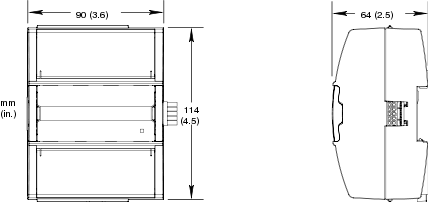
Dimensions including terminal base
|
90 W x 114 H x 64 D mm (3.6 W x 4.5 H x 2.5 D in.)
|
|
|
Weight including terminal base
|
0.269 kg (0.59 lb)
|
Weight excluding terminal base
|
0.146 kg (0.32 lb)
|
Terminal base
|
TB-IO-W1
|
| Universal inputs | |
|
|
Absolute maximum ratings
|
-0.5 to +24 VDC
|
| RTD temperature | |
Reliability check
|
Yes
|
Supported RTDs
|
Pt100, Pt1000, Ni1000, LG-Ni1000, and JCI-Ni1000
|
| Pt100 | |
Range
|
-50 to +150 °C (-58 to +302 °F)
|
Measurement accuracy
|
+/-0.3 °C (+/-0.54 °F)
|
Resolution
|
0.03 °C (0.05°F)
|
| Pt1000 | |
Range
|
-50 to +150 °C (-58 to +302 °F)
|
Measurement accuracy
|
+/-0.2 °C (+/-0.36 °F)
|
Resolution
|
0.03 °C (0.05 °F)
|
| Ni1000 | |
Range
|
-50 to +150 °C (-58 to +302 °F)
|
Measurement accuracy
|
+/-0.1 °C (+/-0.18 °F)
|
Resolution
|
0.03 °C (0.05 °F)
|
| LG-Ni1000 | |
Range
|
-50 to +150 °C (-58 to +302 °F)
|
Measurement accuracy
|
+/-0.1 °C (+/-0.18 °F)
|
Resolution
|
0.03 °C (0.05 °F)
|
| JCI-Ni1000 | |
Range
|
-50 to +150 °C (-58 to +302 °F)
|
Measurement accuracy
|
+/- 0.1 °C (+/- 0.18 °F)
|
Resolution
|
0.03 °C (0.05 °F)
|
| RTD temperature wiring | |
Maximum wire resistance
|
20 ohm/wire (40 ohm total)
|
Maximum wire capacitance
|
60 nF
|
| The wire resistance and capacitance typically corresponds to a 200 m wire. | |
| RTD resistive | |
Reliability check
|
Yes
|
| 100 ohm | |
Range
|
50 to 220 ohm
|
Including wiring resistance
|
|
Measurement accuracy
|
+/-(0.08 + 2 x 10
-4
x R) ohm
|
| R = resistance in ohm | |
Resolution
|
0.01 ohm
|
| 1,000 ohm | |
Range
|
500 to 2,200 ohm
|
Including wiring resistance
|
|
Measurement accuracy
|
+/-(0.3 + 2 x 10
-4
x R) ohm
|
| R = resistance in ohm | |
Resolution
|
0.1 ohm
|
| RTD resistive wiring | |
Maximum wire capacitance
|
60 nF
|
| Digital | |
Range
|
Dry contact switch closure or open collector/open drain, 24 VDC, 2.4 mA
|
Minimum pulse width
|
120 ms
|
LED polarity
|
Software selectable, if the LED is activated when the input is high or low
|
LED color
|
Red or green, software selectable
|
| Counter | |
Range
|
Dry contact switch closure or open collector/open drain, 24 VDC, 2.4 mA
|
Minimum pulse width
|
20 ms
|
Maximum frequency
|
25 Hz
|
LED polarity
|
Software selectable, if the LED is activated when the input is high or low
|
LED color
|
Red or green, software selectable
|
| Resistive | |
Range
|
0 to 15,000 ohm
|
Accuracy
|
+/-(3 + 6 x 10
-4
x R) ohm
|
| R = resistance in ohm | |
Resolution
|
1 ohm
|
Reliability check
|
Yes
|
Maximum wire capacitance
|
60 nF
|
Central IO Modules
Input Modules
2-Wire or 3-Wire RTD Temperature Input Value and Reliability Levels
2-Wire RTD Temperature Input Wiring Resistance