
How to
Installing an Electronics Module on a Terminal Base
You install an electronics module directly onto the relevant terminal base, where it will connect to the power supply and address bus.
The devices are designed mainly for installing on DIN rails in a cabinet.
Consider a simple example:

System ex. 1. A Power supply, an Automation Server, and two I/O modules
Each device consists of two parts:
Terminal base
Electronics module

A hardware device: the electronics module and the terminal base
A separate terminal base means the terminal base can be installed and wired before the electronics module with the application program and data is supplied.
The terminal base is usually installed on a DIN rail, but it can also be mounted directly on the wall. The electronics module is easily plugged in to the terminal base and firmly locked by pushing the handles in place.
Replacing an electronics module is done in seconds because no terminal wiring is affected.
DIN Rail Installation
Install the terminal bases on a horizontal DIN rail.

Terminal base installed on a horizontal DIN rail
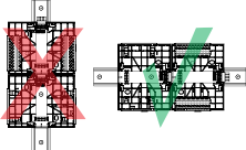
A DIN rail is a common and convenient technique for installing a SmartX device along with other associated control and monitoring devices. The most efficient ventilation is achieved with the wall-mounted DIN rail oriented horizontally and with adequate space provided between the SmartX device rail and adjacent rails or other panel-mounted devices.
The terminal bases are connected to each other by sliding the terminal bases together using the built-in connectors.
To ensure that the correct electronics module is used with the correct terminal base, you must always check that the warning label on the terminal base backplane indicates which module type is to be connected. Write the intended module type, if it is not already printed, on the label.

Terminal base with label for intended module type
Install only the module type that is indicated on the label on the terminal base backplane. A mismatch can cause electric shock and damage the electronics module.
 Warning
If the label does not indicate the intended module type, consult the control panel documentation to determine the intended module type.
To prevent the modules from sliding sideways on the DIN rail, fix an end clamp for DIN 35 (part number SXWDINEND10001) tightly against the rightmost device on the rail. The end clamp is easily removed if you bend the snap lock open with a screwdriver.

End clamp for DIN 35 fixed across the DIN rail
The chain of devices can be split on multiple DIN rails (rows) by using an extension cord called S-cable. Maximum five S-cables are allowed per system. The S-cable connects the last (rightmost) device on one DIN rail with the first (leftmost) device on the next DIN rail. The complete chain of devices must remain within one cabinet for EMC reasons.
The following figure shows an example of how you can use an S-cable to connect devices that are installed on separate DIN rails in a cabinet. For sufficient cooling air flow through the devices, the DIN rails and the devices are installed horizontally in the cabinet.

Devices installed on separate, horizontal rails and connected using an S-cable
The S-cable is available with right angle connectors and in 1.5 m (5 ft) and 0.75 m (2 ft 5 in) lengths. You can serially connect up to two S-cables to extend the length.
The following image shows the minimum space required for plugging/unplugging the S-cable from the device but also provides information on the minimum bend radius required to reduce the stress of the cable. The S-cable with straight connectors is a discontinued product, which can no longer be ordered from Schneider Electric.

S-cable connecting devices on separate rails
Device Order
The order in which the devices are installed in the chain (I/O bus) is important. The devices should be installed in the following order:
Position 1 (leftmost): Power supply (mandatory)
Position 2: AS-P or Automation Server (mandatory)
Position 3-32: I/O modules and extra power supplies as needed based on power budget. One power supply can supply power for loads up to 30 W. For more information, see Power Budget .
There is a limit of one SmartStruxure server device per I/O bus.
The rules are summarized in the following illustration.

Order of devices on the I/O bus
You can reuse an Automation Server terminal base (TB-AS-W1) for an AS-P module by removing the terminal block at the top of the terminal base.
Pull out the two handles on the left and right sides of the module.
Plug in the module to the terminal base, ensuring that the PCB header pins align correctly with the backplane socket, and press firmly.
Push the handles in firmly to lock the module in place.
action_zoom_plus_stroke 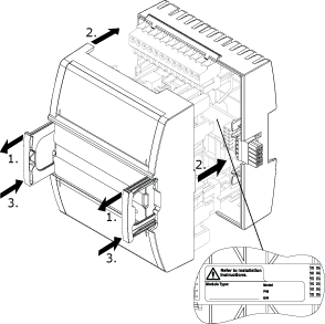
Open the clear plastic label carriers.
action_zoom_plus_stroke 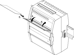
Write and insert the labels.
Close the label carriers.
You can now power up the device.
 Device Installation
 General Hardware Configuration Problem
No Communication with SmartStruxure Server Device
No Communication with I/O Module
Powering Up a Device
Printing a Label to Identify I/O Channels
Electronics Modules
General Hardware Configuration Problem
No Communication with SmartStruxure Server Device
No Communication with I/O Module
Powering Up a Device
Printing a Label to Identify I/O Channels
Electronics Modules