
How to
Powering Up MP-V
You perform the following steps to power up MP-V.
The MP-V incorporates an integral actuator and the device is designed for over-the-shaft damper installation.

MP-V installed over the damper shaft
The MP-V can be used with dampers that are opened in clockwise (CW) position as well as dampers opened in counter-clockwise (CCW) position. You use WorkStation or the Commission mobile application to configure the MP-V actuator direction of rotation accordingly.

MP-V components
The MP-V is typically installed with the air flow sensor barbed fittings pointing down (orientation B in the figure below). The MP-V can also be installed with the barbed fittings pointing left (A), right (C), or up (D).

Supported installation orientations
With a downward extension, the available area around the damper shaft must measure:
160 mm (6 inches) down from the lower edge of the shaft,
120 mm (4.5 inches) to the right,
45 mm (1.75 inches) to the left, and
45 mm (1.75 inches) above the shaft.
Ensure that the location allows enough clearance for servicing.
The MP-V actuator is designed to be installed over a 12.7 mm (0.5 inch) diameter round damper shaft with a minimum of 54 mm (2.125 inches) exposed damper shaft length.
When the damper shaft diameter is less than 12.7 mm (0.5 inch), an adapter is required. An adapter with part number AM-135 can be ordered from Schneider Electric to enable installation on a 9.5 mm (0.375 inches) diameter damper shaft.

AM-135 damper shaft adapter
The cutout section of the shaft adapter must be positioned such that the damper shaft mounting screws are tightened against the damper shaft and not the adapter cylinder.
When the exposed damper shaft length is less than 54 mm (2.125 inches) but greater than 22.2 mm (0.875 inch), you move the damper shaft mounting screws from the actuator collar to the alternative screw holes on the MP-V actuator.

Alternative position of the mounting screws for shorter damper shaft lengths
The MP-V also has two mounting brackets, which allow you to choose the mounting bracket that best accomodates the available access space in the VAV mounting area. You position the anti-rotation clip in the desired mounting bracket.

Two mounting brackets
The MP-V onboard air flow sensor is connected to an air velocity probe in the VAV box using two tubes. A dip in the tubing helps prevent moisture from entering the MP-V and damaging the air flow sensor. The dip should extend below the elevation of the barbed fittings. This applies to all MP-V orientations, but especially C and D.

Tubing dip
The MP-V is delivered with terminal blocks installed on the device. Spare terminal blocks can be ordered separately using the part number SXWMPVCON10001.
The terminal blocks are removable. You can quickly and easily replace an MP-V because no terminal wiring is affected.
When the MP-V is powered up for the first time, the MP-V software automatically performs an actuator travel and damper position calibration. The calibration operation drives the damper actuator in the close direction and registers the position when the actuator encounters the stop. The software then drives the actuator in the open direction and registers the position when the stop is encountered. The software uses that information to scale the 0 to 100% span. Mechanical obstructions hindering the damper actuator rotation during the calibration process can adversely affect the calibration results and thus the VAV damper operation. In that case, you can manually run a recalibration. For more information, see Configuring a Damper Command .
Initial calibration of actuator travel and damper position is performed automatically when the MP-V is powered up for the first time. If you subsequently press the manual override button, you must recalibrate the MP-V manually. For more information, see Configuring a Damper Command .
Ensure that the MP-V is properly installed and secured.
Check that all wiring is correct.
Ensure that terminal number 1 is connected to the 24 VAC input lead from a separate, isolated 24 VAC transformer.
action_zoom_plus_stroke 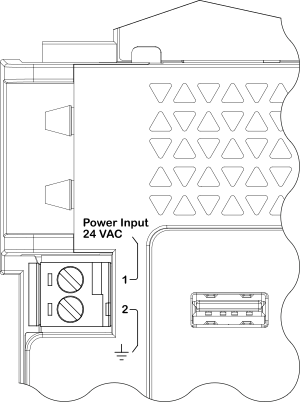
Ensure that terminal number 2 is connected to the same earth ground connection as the common (low/ground) lead from the 24 VAC transformer secondary.
After powering up, check that the Status LED changes to a constant green light after about a minute.
 MP-V Device Installation
MP-V Built-in Power Supply
Grounding and Power for Systems with MP Controllers
MP-V Screw Terminals
MP-V-7A Screw Terminals
MP-V-9A Screw Terminals
Installing MP-V on a Damper that Rotates Counter-Clockwise (CCW) to Open
MP-V Device Installation
MP-V Built-in Power Supply
Grounding and Power for Systems with MP Controllers
MP-V Screw Terminals
MP-V-7A Screw Terminals
MP-V-9A Screw Terminals
Installing MP-V on a Damper that Rotates Counter-Clockwise (CCW) to Open
 No Power or MP-V Does Not Turn On
MP Controller LEDs
No Power or MP-V Does Not Turn On
MP Controller LEDs
 Status LEDs
Configuring a Damper Command
Status LEDs
Configuring a Damper Command