Concept
Backplane Board
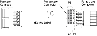
A backplane board is mounted in the terminal base for the W1 width devices. The backplane board is equipped with two 2x5-pin bus connectors, a 2x6-pin electronics module connector, address logic circuitry, and a device label.

Backplane board
There are two versions of the backplane board:
The AS-P, Automation Server, and I/O module version passes power through from the left to the right connector.
The power supply version does not pass power through from the left to the right connector.
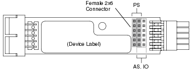
The two backplane board versions incorporate different locations of the 2x6 electronics module connector. This arrangement prevents power interference problems if one or more power supplies are unintentionally installed on terminal bases that are designed for the AS-P, Automation Server, or I/O modules.
2x5 Connector
The right connector establishes connection with the left connector of the next terminal base when the terminal bases are connected together.

Pinout for the left and right 2x5 connectors, seen from the outside
The pins are used as follows:
|
Pin number |
|
Pin number |
|
|
5 |
Address bit #4 (MSB) |
10 |
+24 V backplane power |
|
4 |
Address bit #3 |
9 |
+24 V bus power |
|
3 |
Address bit #2 |
8 |
GND |
|
2 |
Address bit #1 |
7 |
RS-485 – bus communication |
|
1 |
Address bit #0 |
6 |
RS-485 + bus communication |
2x6 Connector
The internal connector fetches or supplies power from/to the electronics module that is installed on the terminal base.

Pinout for the 2x6 connector

The 2x6 connector and its two positions
For the power supply, the connector resides in the left position and the pins are used as follows:
|
Pin number |
|
Pin number |
|
|
12 |
+24 V power to bus |
11 |
GND |
|
10 |
+24 V power to bus |
9 |
GND |
|
8 |
+24 V backplane power |
7 |
Address bit #3 |
|
6 |
Address bit #4 (MSB) |
5 |
Address bit #2 |
|
4 |
RS-485 – bus communication |
3 |
Address bit #1 |
|
2 |
RS-485 + bus communication |
1 |
Address bit #0 |
For the AS-P, Automation Server, and I/O modules, the connector resides in the right position and the pins are used as follows:
|
Pin number |
|
Pin number |
|
|
12 |
GND |
11 |
+24 V bus power |
|
10 |
GND |
9 |
+24 V bus power |
|
8 |
Address bit #3 |
7 |
GND |
|
6 |
Address bit #2 |
5 |
Address bit #4 (MSB) |
|
4 |
Address bit #1 |
3 |
RS-485 – bus communication |
|
2 |
Address bit #0 |
1 |
RS-485 + bus communication |
Address Logic Circuitry
The backplane board includes circuitry that provides the electronics module that is installed on the terminal base with a 5-bit address. The address circuitry on the backplane receives its power from the +24 V backplane power. This is separated from the +24 V bus power.
I/O Module Address Calculation
An I/O modue 5-bit address is generated on the backplane Printed Circuit Board (PCB), which is mounted in the terminal base. 5-bits are required to generate physical addresses 0 - 31. The AS-P, Automation Server, and I/O module read the physical address and add 1 internally to yield logical addresses from 1 - 32, which display as slot IDs in Building Operation. The 5-bit address defines the maximum of 32 modules in a system. Although the Power Supply (PS-24V) uses an address, the device is not "smart." Therefore, the Power Supply does not communicate on the I/O bus or respond to packets on the I/O bus but consumes an address on the I/O bus.
The vertical 2x6 PCB connector on the backplane PCB provides power, ground, communication, and the 5-bit address to an I/O module plugged into the terminal base.
The backplane PCB accepts an input address from the male connector located on the left side of the terminal base. The backplane PCB circuitry adds 1 to the address passed to it from the left connector and outputs it on the female connector on the right side. As more terminal bases are added to a system, the address increases from left to right.
The AS-P, Automation Server, and I/O module read the address by way of the vertical backplane female connector. The address read by the I/O electronics is also output on the right-hand side female connector.
The first terminal base on an I/O bus cannot have another terminal base plugged into its male backplane connector. Therefore, internal programming resistors force the first physical address to be zero (0) at the female connector, which is the logical address 1. For pin usage, refer to the 2x5 and 2x6 connector tables in this topic.
Device Label
The device label on the backplane board is used for writing down what type of electronics module is intended to be connected to the terminal base.
 Hardware Overview
 Terminal Bases
 I/O Bus Parts
 Power Budget