
How to
Connecting a Non-isolated RS-485 Adapter
You connect a Non-isolated RS-485 Adapter (via a separate connection cable) to a BACnet/IP controller to convert the controller RS-485 RJ45 interface to screw terminals, which is required to connect the controller to a BACnet MS/TP (RS-485) network. You use a Non-isolated RS-485 Adapter (SXWNISORS48510001) when the BACnet MS/TP network includes non-isolated controllers, such as the b3 BACnet family of zone controllers.
The Non-isolated RS-485 Adapter is equipped with an RJ45 port for connection to a BACnet/IP controller RS-485 Com port and a 4-position removable screw terminal block for connection to a BACnet MS/TP (RS-485) network.

RJ45 port and screw terminals, Non-isolated RS-485 Adapter
The following figure shows an example of how a Non-isolated RS-485 Adapter is connected to one of the RS-485 Com ports (RJ45) of an RP-C controller via a Cat 5 (or higher) UTP cable of maximum length 0.3 m (12 in.) and how the BACnet MS/TP network (RS-485) wires from the adapter are connected to the RS-485 Com port screw terminals of an AS-P server.

Example with a Non-isolated RS-485 Adapter used for connection of an RP-C controller to a BACnet MS/TP network and an AS-P server
A separate connection cable is required to connect the RJ45 port on the RS-485 adapter to the RS-485 Com port (RJ45) on the BACnet/IP controller. The cable is not included and needs to be purchased separately.
Use a Cat 5 (or higher) unshielded, straight-through wired cable with eight conductors (four twisted pairs) and RJ45 connectors. Use a cable with the wire size (cross-sectional area) 22 to 26 AWG (0.34 to 0.14 mm²), a maximum length of 0.3 m (12 inches), and a rating that meets the requirements of the target environment. For example, when devices are installed in a space that handles conditioned air or return air, the cables typically need to be plenum-rated.
For more information, see Connecting a Non-isolated RS-485 Adapter .
For more information, see RJ45 Pinout for the RS-485 Ports of the RP-C Controller .
The four screw terminals are wired and connected to a BACnet MS/TP (RS-485) network as described in the following table.
Recommended screw tightening torque: 0.5 Nm (4.5 lbf.in)
|
Terminal |
Usage |
|
NOT USED |
Not connected. |
|
TX/RX+ |
Data line (+) for connection to the TX/RX+ signal in the BACnet MS/TP twisted pair connecting all devices on the bus. |
|
TX/RX– |
Data line (–) for connection to the TX/RX– signal in the BACnet MS/TP twisted pair connecting all devices on the bus. |
|
SHIELD |
Convenience terminal to interconnect two shield drain wires (incoming and outgoing). There is no electrical connection in the adapter. The shield should be connected to ground at only one location and that is recommended to be at the automation server. The shield should not be connected directly to the RET terminal on the automation server. The transient energy on the drain wire should be conducted to ground and not through the automation server. |
For more information, see Wiring the Screw Terminals on a Non-isolated RS-485 Adapter .
For more information, see RS-485 Communications .
Connect a Cat 5 (or higher) unshielded, straight-through wired cable with eight conductors (four twisted pairs) with RJ45 connectors to the RJ45 receptacle on the RS-485 adapter.
Use a cable with the wire size (cross-sectional area) 22 to 26 AWG (0.34 to 0.14 mm²), a maximum length of 0.3 m (12 inches), and a rating that meets the requirements of the target environment, for example, plenum space.
Note:The cable is not included.
Connect the other end of the cable to the RP controller RS-485 Com A or Com B port or the MP-V controller Com A port.
Select the RS-485 Com port that is configured for BACnet MS/TP (RS-485) network. For more information, see RP-C BACnet MS/TP Support .For more information, see Allocating Flexible Ports .
action_zoom_plus_stroke 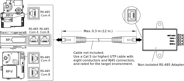
You can now install and wire the RS-485 adapter.
 Non-isolated RS-485 Adapter Connection and Wiring
RP-C BACnet MS/TP Support
Allocating Flexible Ports
Installing an RS-485 Adapter
Wiring the Screw Terminals on a Non-isolated RS-485 Adapter
Non-isolated RS-485 Adapter Connection and Wiring
RP-C BACnet MS/TP Support
Allocating Flexible Ports
Installing an RS-485 Adapter
Wiring the Screw Terminals on a Non-isolated RS-485 Adapter