
How to
Powering Up MP-C
You perform the following steps to power up an MP-C.
The MP-C can be installed on a DIN rail or other flat surface inside a cabinet.
A DIN rail is a common and convenient technique for installing the MP-C along with other associated control and monitoring devices. The most efficient ventilation is achieved with the wall-mounted DIN rail oriented horizontally and with adequate space provided between the MP-C rail and adjacent rails or other devices.
The MP-C is typically installed horizontally (on a DIN rail going from left to right), with the device label text in the upright position reading left to right.

MP-C installed on a horizontal DIN rail
The restrictions on installing the device in other orientations differ depending on the operating conditions.
Under normal operating conditions of 0 to 50 °C (32 to 122 °F), the MP-C can be installed in the following orientations:
Horizontally (on a DIN rail going from left to right), with the device label text in the upright position reading left to right. See “a” in the following figure.
Vertically (on a DIN rail going from top to bottom), which means that the device is rotated +90 degrees or -90 degrees from the horizontal position. See “b” and “c” in the following figure.
Installing the MP-C rotated 180 degrees from the horizontal position with device label text up and down (“e” in the figure), face down from a ceiling (“d” in the figure), or face up on a horizontal surface (“f” in the figure) is not supported.
")
Installation orientation restrictions for the MP-C operated in normal conditions, 0 to 50 °C (32 to 122 °F)
When the MP-C is used for rooftop applications, -40 to +60 °C (-40 to +140 °F), the device should be installed horizontally, with the device label text in the upright position reading left to right. See “a” in the following figure. Any other installation orientation (“b”, “c”, “d”, “e”, and “f” in the figure) may exceed the controller's thermal specifications, which can damage the controller.
")
Installation orientation restrictions for the MP-C operated at -40 to +60 °C (-40 to +140 °F)
The MP-C can be installed in a standard DIN enclosure.
When installing MP-Cs in a cabinet, it is recommended to provide ample space between the DIN rails and controllers for sufficient ventilation.

MP-Cs installed on horizontal DIN rails in a cabinet
To help prevent the device from sliding down or sideways on the DIN rail, install an end clip for DIN 35 (part number SXWDINEND10001) tightly against the bottom or rightmost device on the rail. The end clip is easily removed if you bend the snap lock open with a screwdriver.

End clamp for DIN 35 fixed across the DIN rail
The MP-C is delivered with terminal blocks installed on the device. Spare terminal blocks can be ordered separately using the part number SXWMPCCON10001.
The terminal blocks are removable. You can replace an MP-C in seconds because no terminal wiring is affected. The only exception is the high power relay outputs on the MP-C-15A and MP-C-18A models, which use a two-position fixed terminal block due to current requirements.
All MP-C models can be equipped with MP-C Display (part number SXWMPCDSP10001), which is an add-on module that enables manual override control of analog and digital outputs. The module consists of an LCD display and keys. The module is designed for permanent installation.

MP-C Display installed on MP-C
Do not try to remove the MP-C Display module as it may damage the enclosure and the module. Once installed, the MP-C Display module cannot be removed.
Check that all wiring is correct.
Ensure that the 24 VAC at 50/60 Hz or 24-30 VDC power is supplied to terminals 1 and 2.
action_zoom_plus_stroke 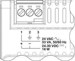
Ensure that the ground cable is connected to terminal number 3.
After powering up, check that the Status LED changes to a constant green light after about a minute.
 MP-C Device Installation
MP-C Built-in Power Supply
Grounding and Power for Systems with MP Controllers
MP-C Screw Terminals
MP-C-15A Screw Terminals
MP-C-18A Screw Terminals
MP-C-18B Screw Terminals
MP-C-24A Screw Terminals
MP-C-36A Screw Terminals
MP Controller LEDs
MP-C Device Installation
MP-C Built-in Power Supply
Grounding and Power for Systems with MP Controllers
MP-C Screw Terminals
MP-C-15A Screw Terminals
MP-C-18A Screw Terminals
MP-C-18B Screw Terminals
MP-C-24A Screw Terminals
MP-C-36A Screw Terminals
MP Controller LEDs
 Status LEDs