
Specifications
RP-C-EXT-BL-2-LV-PD

RP-C-EXT-BL-2-LV-PD – Low-voltage blind module
Introduction
SpaceLogic* RP-C-EXT-BL-2-LV-PD blind module connects to the SpaceLogic RP room controllers and provides I/O expansion for low-voltage blind control.
The low-voltage blind module enables control and power supply (24 VDC) of motorized window blinds and shutters.
The blind module is part of the RP controller expansion modules for connected room solution and can be combined with other modules from this product range.
* Formerly known as SmartX.
Features
The low-voltage blind module has the following features:
Power and communications through the room bus
Two motor control outputs for control of 24 VDC powered blinds (opening, closing, positioning)
Four digital inputs for connection of blind switches and window contacts. The digital inputs are SELV (Safety Extra-Low Voltage).
Measurement of energy consumption per module
Wieland connectors for quick and easy installation
Engage mobile application for room comfort settings
Status LED for the device
One status LED for each blind output
Rotary switch for address configuration
The RP controller room bus allows RP controller expansion modules to be connected to the controller for people counting, motion detection, luminosity and sound pressure level measurements, Bluetooth Low Energy based applications, and control of electric lights and window blinds.
The RP-C Pro controller room bus supports up to nine connected RP controller expansion modules with the following restrictions:
Maximum of two DALI light modules
Maximum of two SMI blind modules
Maximum of seven Multi-sensor or Insight-Sensor devices
The RP-C Advanced controller room bus supports up to six connected RP controller expansion modules with the following restrictions:
Maximum of two DALI light modules
Maximum of two SMI blind modules
Maximum of four Multi-sensor or Insight-Sensor devices
Maximum total length of the room bus is 72 m (236 ft).
The Engage mobile application enables control of room temperature, fan speed, lights, and blinds/shades directly from a smartphone. A user can manage these settings when the application is connected to the RP-C controller.
The Engage mobile application is free and available for download from Google Play and Apple App Store.
For more information, see the Engage Specification Sheet.
|
Product |
Part number |
|
RP-C-EXT-BL-2-LV-PD
|
SXWREB2LVPD10001
|
|
DIN-RAIL-CLIP, DIN-rail end clip
package of 25 pieces
|
SXWDINEND10001
|
Specifications
| Electrical | |
Nominal voltage
|
230 VAC
|
Operating voltage range
|
+/-10 %
|
Frequency
|
50/60 Hz
|
Power consumption
|
75 VA
|
Room bus power consumption
|
0.3 W (24 VDC)
|
Protection
|
Maximum 16 A external fuse (circuit breaker) is needed
|
Overvoltage category
|
III
|
| Onboard 24 VDC power supply | |
| RP-C-EXT-BL-2-LV-PD has an onboard 24 VDC power supply that is used to power the blind outputs. | |
Nominal voltage
|
24 VDC
|
Maximum supply current
|
1.3 A
|
Protection
|
Short-circuit protection
|
| Environment | |
Ambient temperature, operating
|
0 to 40 °C (32 to 104 °F)
|
Ambient temperature, storage
|
-20 to +70 °C (-4 to +158 °F)
|
Humidity
|
20 to 90 % RH non-condensing
|
Pollution degree
|
2
|
| Material | |
Plastic flame rating
|
UL94 V-0
|
Ingress protection rating
|
IP 20
|
| Mechanical | |
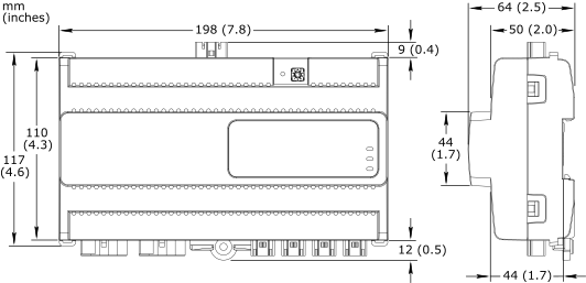
Dimensions
|
198 W x 110 H x 64 D mm (7.8 W x 4.3 H x 2.5 D in.)
|
|
|
Weight
|
0.399 kg (0.880 lb)
|
Installation
|
DIN rail or flat surface
a
|
| a) For information on installation orientation restrictions, see the SpaceLogic Hardware Reference Guide. | |
Connectors
|
Power input: 1 x 3-pin Wieland GST15i3 connector
|
Blind outputs: 2 x 5-pin Wieland GST15i5 connector
|
|
Digital inputs: 4 x 2-pin Wieland GST15i2 connector
|
|
| Software compatibility | |
EcoStruxure Building Operation software
|
version 3.1 and later
|
| Agency compliances | |
Emission
|
RCM; BS/EN 61000-6-3; BS/EN 50491-5-2; FCC Part 15, Sub-part B, Class B
|
Immunity
|
BS/EN 61000-6-2; BS/EN 50491-5-3
|
Safety standards
|
BS/EN 60730-1; BS/EN 60730-2-11; BS/EN 50491-3
|
| Communication ports | |
Room bus
|
RS-485
|
Dual RJ45 ports for daisy-chain configurations
|
|
Use a Cat 5 (or higher) cable
|
|
Maximum total length of the room bus: 72 m (236 ft)
|
|
Room bus protection
|
Transient voltage suppressors on communication and power signals
|
| Hardware | |
CPU type
|
ARM Cortex-M4 single-core
|
Frequency
|
80 MHz
|
SRAM (embedded)
|
320 KB
|
Flash memory (embedded)
|
512 KB
|
NOR flash memory
|
16 MB
|
Status indicator
|
LED (green and red) that shows the status of the device
|
Blind status indicator
|
One status LED (green) for each output
|
Address switch
|
Rotary switch 0 to 9
|
Set button
|
Push-button switch
|
| Energy metering | |
| Energy consumption measurement | |
| The energy consumption is measured in Wh, shared by the two outputs. | |
Accuracy class (according to IEC 61557-12)
|
Active energy measurement: Class 1
|
Typical measurement accuracy at room temperature
|
0.5 to 2 W: 5%
|
2 to 30 W: 1%
|
|
| Blind outputs | |
| Motor control outputs for 24 VDC powered blind motors with automatic end stop detection. An end stop at the top position is required. An end stop at the bottom position is recommended. | |
Outputs
|
2, Blind 1 to Blind 2
|
Output terminals
|
M- and M+
|
Power distribution
|
24 VDC
|
Maximum 1 A load per output
|
|
Maximum 1.3 A total load for the 2 outputs
|
|
Maximum 2 A starting current (<100 ms) per output
|
|
| Digital inputs | |
Inputs
|
4, DI1 to DI4
|
Range
|
Dry contact, 0 to 5.0 VDC, 2.2 mA, SELV (Safety Extra-Low Voltage)
|
Connections
Follow proper installation wiring diagrams and instructions. For more information on wiring, see Hardware Reference Guide.

RP-C-EXT-BL-2-LV-PD
|
Use |
Part number |
Reference |
Connector type |
Suitable for cable diameters mm (inches) |
Marking |
Color of coding /housing |
Minimum order quantity |
|
Power supply input |
SXWRPCCONWWPOW |
91.931.4053.1 |
Female |
5.6–11 (0.22–0.43) |
L, PE, N |
Black /Black |
100 |
|
Blind outputs |
SXWRPCCONWBLLV |
91.952.4353.0 |
Male |
8.5–12.5 (0.34–0.49) |
5, 4, 3, 2, 1 5, 4, 3: Not used 2: M- 1: M+ |
Light blue /White |
50 |
|
Digital inputs |
SXWRPCCONWDI |
91.921.2353.0 |
Female |
3.4–5.5 (0.14–0.21) |
1, 2 1: DI1..4 2: RET |
Light blue /White |
100 |
The external connectors need to be ordered separately. The connectors can be ordered in quantities of 50 or 100 from Schneider Electric using the above part numbers. The connectors can also be ordered directly from Wieland using the above reference numbers. For more information, see the Wieland Electric web site.
Compatibility with the type and characteristics of the blind motors should be verified at an early stage in your project. In case of uncertainty, additional testing may be required.
RP-C Advanced
RP-C-EXT-MS-BLE
RP-C-EXT-DALI-M-PD
RP-C-EXT-0-10V-4-PD
RP-C-EXT-BL-4-HV-PD
RP-C-EXT-BL-SMI-2-LV-PD
RP-C-EXT-BL-SMI-4-HV-PD
RP-C-EXT-DALI
RP-C-EXT-0-10V-4
RP-C-EXT-REL-4
Commission
Engage