
Specifications
RP-C-EXT-DALI-M-PD

RP-C-EXT-DALI-M-PD – DALI light module
Introduction
SpaceLogic* RP-C-EXT-DALI-M-PD light module connects to the SpaceLogic RP room controllers and provides I/O expansion for lighting control with DALI (Digital Addressable Lighting Interface).
The DALI light module enables power supply and control of lights equipped with DALI ballasts (DALI control gear).
The DALI light module is a DALI-2 certified control device (application controller) with multi-master capability. DALI-2 compliance means benefits such as improved interoperability and easier installation and maintenance. The DALI light module can be used with DALI version-1 products because DALI-2 is designed to be backward compatible with DALI version-1. The multi-master capability of the DALI light module allows the module to function as a DALI master in a DALI network and can thus work together with DALI-2 sensors and push-buttons.
Lighting can be controlled by the RP-C through motion detection and light intensity measurement provided by the Multi-sensor or by SpaceLogic Sensors connected to the RP-C.
The DALI light module is part of the RP controller expansion modules for connected room solution and can be combined with other modules from this product range.
* Formerly known as SmartX.
Features
The DALI light module has the following features:
Power and communications through the room bus
DALI-2 certified control device (application controller)
DALI multi-master function for communication with DALI sensors and push-buttons on the DALI bus, which minimizes wiring and installation costs
Group and individual addressing of DALI control gear (lights)
One DALI channel, which is split into four inputs/outputs, for DALI bus power supply and control of up to 32 lights and 16 input devices (the maximum number of lights and input devices per input/output is determined by the maximum inrush current)
Up to 16 DALI groups for common control of lights
Up to 16 DALI input devices in total. Each input device supports up to four sensors or buttons.
Four digital inputs for connection of light switches and window contacts. The digital inputs are SELV (Safety Extra-Low Voltage).
Measurement of energy consumption per module
Suitable for mounting in ceilings
Wieland connectors for quick and easy installation
Engage mobile application for room comfort settings
Status LED for the device
One status LED for each DALI input/output
Rotary switch for address configuration
The DALI inputs/outputs are connected to the power supply network through the DALI light module. For the DALI bus wires, you may use the standard installation equipment permitted for ELV (Extra-Low Voltage) installations. The DALI bus meets SELV (Safety Extra-Low Voltage) requirements.
The DALI-2 interface has the following features:
DALI groups can combine lights regardless of which outputs the lights belong to.
Lights that belong to the same DALI group are controlled simultaneously for switching on/off, dimming, and color temperature (tunable white) adjustment
Management of ballast and lamp alarms
Automatic addressing of lights
The RP controller room bus allows RP controller expansion modules to be connected to the controller for people counting, motion detection, luminosity and sound pressure level measurements, Bluetooth Low Energy based applications, and control of electric lights and window blinds.
The RP-C Pro controller room bus supports up to nine connected RP controller expansion modules with the following restrictions:
Maximum of two DALI light modules
Maximum of two SMI blind modules
Maximum of seven Multi-sensor or Insight-Sensor devices
The RP-C Advanced controller room bus supports up to six connected RP controller expansion modules with the following restrictions:
Maximum of two DALI light modules
Maximum of two SMI blind modules
Maximum of four Multi-sensor or Insight-Sensor devices
Maximum total length of the room bus is 72 m (236 ft).
The Engage mobile application enables control of room temperature, fan speed, lights, and blinds/shades directly from a smartphone. A user can manage these settings when the application is connected to the RP-C controller.
The Engage mobile application is free and available for download from Google Play and Apple App Store.
For more information, see the Engage Specification Sheet.
|
Product |
Part number |
|
RP-C-EXT-DALI-M-PD
|
SXWREDAMPD10001
|
|
DIN-RAIL-CLIP, DIN-rail end clip
package of 25 pieces
|
SXWDINEND10001
|
Specifications
| Electrical | ||||||||||||||||||||||
Nominal voltage
|
230 VAC
|
|||||||||||||||||||||
Operating voltage range
|
+/-10 %
|
|||||||||||||||||||||
Frequency
|
50/60 Hz
|
|||||||||||||||||||||
Maximum current consumption
|
10 A
|
|||||||||||||||||||||
Room bus power consumption
|
0.3 W (24 VDC)
|
|||||||||||||||||||||
Protection
|
Maximum 16 A external fuse (circuit breaker) is needed
|
|||||||||||||||||||||
Overvoltage category
|
III
|
|||||||||||||||||||||
| Environment | ||||||||||||||||||||||
Ambient temperature, operating
|
0 to 50 °C (32 to 122 °F)
|
|||||||||||||||||||||
Ambient temperature, storage
|
-20 to +70 °C (-4 to +158 °F)
|
|||||||||||||||||||||
Humidity
|
20 to 90 % RH non-condensing
|
|||||||||||||||||||||
Pollution degree
|
2
|
|||||||||||||||||||||
| Material | ||||||||||||||||||||||
Plastic flame rating
|
UL94 V-0
|
|||||||||||||||||||||
Ingress protection rating
|
IP 20
|
|||||||||||||||||||||
| Mechanical | ||||||||||||||||||||||
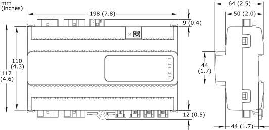
Dimensions
|
198 W x 110 H x 64 D mm (7.8 W x 4.3 H x 2.5 D in.)
|
|||||||||||||||||||||
|
||||||||||||||||||||||
Weight
|
0.433 kg (0.955 lb)
|
|||||||||||||||||||||
Installation
|
DIN rail or flat surface
|
|||||||||||||||||||||
Connectors
|
Power input: 1 x 3-pin Wieland GST15i3 connector
|
|||||||||||||||||||||
DALI inputs/outputs: 4 x 5-pin Wieland GST15i5 connector
|
||||||||||||||||||||||
Digital inputs: 4 x 2-pin Wieland GST15i2 connector
|
||||||||||||||||||||||
| Software compatibility | ||||||||||||||||||||||
EcoStruxure Building Operation software
|
version 4.0 and later
|
|||||||||||||||||||||
| Agency compliances | ||||||||||||||||||||||
Emission
|
RCM; BS/EN 61000-6-3; BS/EN 50491-5-2; FCC Part 15, Sub-part B, Class B
|
|||||||||||||||||||||
Immunity
|
BS/EN 61000-6-2; BS/EN 50491-5-3
|
|||||||||||||||||||||
Safety standards
|
BS/EN 60730-1; BS/EN 60730-2-11; BS/EN 50491-3
|
|||||||||||||||||||||
Digital addressable lighting interface
|
IEC 62386-101; IEC 62386-103
|
|||||||||||||||||||||
| Communication ports | ||||||||||||||||||||||
Room bus
|
RS-485
|
|||||||||||||||||||||
Dual RJ45 ports for daisy-chain configurations
|
||||||||||||||||||||||
Use a Cat 5 (or higher) cable
|
||||||||||||||||||||||
Maximum total length of the room bus: 72 m (236 ft)
|
||||||||||||||||||||||
Room bus protection
|
Transient voltage suppressors on communication and power signals
|
|||||||||||||||||||||
| Hardware | ||||||||||||||||||||||
| Main microcontroller | ||||||||||||||||||||||
CPU type
|
ARM Cortex-M4 single-core
|
|||||||||||||||||||||
Frequency
|
80 MHz
|
|||||||||||||||||||||
SRAM (embedded)
|
320 KB
|
|||||||||||||||||||||
Flash memory (embedded)
|
1024 KB
|
|||||||||||||||||||||
| Memory | ||||||||||||||||||||||
NOR flash memory
|
16 MB
|
|||||||||||||||||||||
| DALI microcontroller | ||||||||||||||||||||||
CPU type
|
ARM Cortex-M0 single-core
|
|||||||||||||||||||||
Frequency
|
32 MHz
|
|||||||||||||||||||||
SRAM (embedded)
|
8 KB
|
|||||||||||||||||||||
Flash memory (embedded)
|
64 KB
|
|||||||||||||||||||||
| Additional hardware | ||||||||||||||||||||||
Status indicator
|
LED (green and red) that shows the status of the device
|
|||||||||||||||||||||
Light status indicator
|
One status LED (green) for each DALI input/output
|
|||||||||||||||||||||
Address switch
|
Rotary switch 0 to 9
|
|||||||||||||||||||||
Set button
|
Push-button switch
|
|||||||||||||||||||||
| Energy metering | ||||||||||||||||||||||
| Energy consumption measurement | ||||||||||||||||||||||
| The energy consumption is measured in Wh, shared by the four outputs. | ||||||||||||||||||||||
Accuracy class (according to IEC 61557-12)
|
Active energy measurement: Class 1
|
|||||||||||||||||||||
Typical measurement accuracy at room temperature
|
20 to 100 W: 5%
|
|||||||||||||||||||||
100 to 3000 W: 1%
|
||||||||||||||||||||||
| DALI inputs/outputs | ||||||||||||||||||||||
Inputs/outputs
|
4, Light 1 to Light 4
|
|||||||||||||||||||||
| The four inputs/outputs share one DALI channel. | ||||||||||||||||||||||
Input/output terminals
|
N, PE, L, DA+, and DA-
|
|||||||||||||||||||||
DALI bus voltage
|
18 VDC
|
|||||||||||||||||||||
Maximum supply current
|
250 mA
|
|||||||||||||||||||||
Guaranteed supply current
|
64 mA
|
|||||||||||||||||||||
Maximum cable length
|
See the SpaceLogic Hardware Reference Guide
|
|||||||||||||||||||||
Power distribution
|
230 VAC (same voltage as power supply)
|
|||||||||||||||||||||
Maximum 5 A load per output
|
||||||||||||||||||||||
Maximum 10 A total load for the 4 outputs
|
||||||||||||||||||||||
Maximum 165 A inrush current (<20 ms) per output
|
||||||||||||||||||||||
Maximum 800 A inrush current (<200 µs) per output
|
||||||||||||||||||||||
| DALI devices | ||||||||||||||||||||||
Supported control gear
|
See table below.
|
|||||||||||||||||||||
|
||||||||||||||||||||||
| a) Color type Tc (Color temperature) of Part 209 of the IEC 62386 standard is supported. | ||||||||||||||||||||||
Supported input device types
|
See table below.
|
|||||||||||||||||||||
|
||||||||||||||||||||||
| a) Parts of the IEC 62386 standard. | ||||||||||||||||||||||
| b) For a list of supported input devices, see the Product Database on the DiiA website, www.dali-alliance.org | ||||||||||||||||||||||
| c) It is recommended to always test an input device at an early stage in a project. | ||||||||||||||||||||||
| Digital inputs | ||||||||||||||||||||||
Inputs
|
4, DI1 to DI4
|
|||||||||||||||||||||
Range
|
Dry contact, 0 to 5.0 VDC, 2.2 mA, SELV (Safety Extra-Low Voltage)
|
|||||||||||||||||||||
Connections
Follow proper installation wiring diagrams and instructions. For more information on wiring, see the SpaceLogic Hardware Reference Guide.

RP-C-EXT-DALI-M-PD
|
Use |
Part number |
Reference |
Connector type |
Suitable for cable diameters mm (inches) |
Marking |
Color of coding /housing |
Minimum order quantity |
|
Power supply input |
SXWRPCCONWWPOW |
91.931.4053.1 |
Female |
5.6–11 (0.22–0.43) |
L, PE, N |
Black /Black |
100 |
|
DALI inputs/outputs |
SXWRPCCONWWLIGHTPD |
91.952.4453.0 |
Male |
8.5–12.5 (0.34–0.49) |
N, PE, L, D2, D1 D2: DA+ D1: DA- |
Pastel blue /White |
50 |
|
Digital inputs |
SXWRPCCONWDI |
91.921.2353.0 |
Female |
3.4–5.5 (0.14–0.21) |
1, 2 1: DI1..4 2: RET |
Light blue /White |
100 |
The external connectors need to be ordered separately. The connectors can be ordered in quantities of 50 or 100 from Schneider Electric using the above part numbers. The connectors can also be ordered directly from Wieland using the above reference numbers. For more information, see the Wieland Electric web site.
RP-C Advanced
RP-C-EXT-MS-BLE
RP-C-EXT-0-10V-4-PD
RP-C-EXT-BL-2-LV-PD
RP-C-EXT-BL-4-HV-PD
RP-C-EXT-BL-SMI-2-LV-PD
RP-C-EXT-BL-SMI-4-HV-PD
RP-C-EXT-DALI
RP-C-EXT-0-10V-4
RP-C-EXT-REL-4
Commission
Engage