
Specifications
RP-C Advanced

RP-C-12C-F-24V
Introduction
SpaceLogic* RP-C is a room-purpose, fully programmable, IP based field controller that suits a wide range of HVAC applications. The RP-C can either be used as a standalone BACnet/IP field controller or as part of an EcoStruxure BMS with a SpaceLogic AS-P or AS-B server or an Enterprise Server as the parent server. The RP-C can also be reconfigured through the EcoStruxure Building Operation software to support BACnet MS/TP, instead of BACnet/IP. The RP-C features a wireless chip, which enables commissioning of the controller with the Commission mobile application and allows tenants to change the room comfort settings using their smartphones with the Engage mobile application. Web services enable web access directly to the RP-C, making the controller an open IoT hub in the room or space area.
The RP-C has the following features:
IP enabled with dual-port Ethernet switch
Full range of controller models
Versatile onboard I/O point mix
Optional covers
Wireless connectivity
Advanced monitoring
Two configurable RS-485 ports
Sensor bus for living space sensors
Room bus for Connected Room Solutions
Modbus RTU subnetwork
KNX support (KNX Modbus gateway required)
BACnet MS/TP support (adapter required)
Engage mobile application for room comfort settings
Commission mobile application for commissioning of the controller before the BMS is in place
Full EcoStruxure Building Operation software support, providing efficient engineering tools
Web services through RESTful API
* Formerly known as SmartX.
IP connectivity and flexible network topologies
The BACnet/IP controllers are based on open protocols that simplify interoperability, IP configuration, and device management:
IP addressing
BACnet/IP communications
DHCP for easy network configuration
The BACnet/IP controllers have a dual-port Ethernet switch, which enables flexible network topologies:
Star
Daisy chain
Rapid Spanning Tree Protocol (RSTP) ring
In a star topology, the controller and the parent EcoStruxure BMS server are individually connected to an Ethernet switch. Daisy-chain multiple controllers together to reduce installation time and cost. When using a ring network topology, in the event of a broken IP network or a non-operational controller, RSTP will enable rapid identification of the location of the detected error while maintaining communication with the controllers on either side of the break.
Full range of controller models
The RP-C Advanced range includes four different models, which offer four different sets of I/O point types, named 12A, 12B, 12C, and 16A. The RP-C-12A, -12B, and -12C models support 24 VAC/DC power supply, whereas the RP-C-16A model is a 230 VAC model.
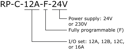
Fully programmable
The fully programmable RP-C models provide flexibility through support of both Script and Function Block programming options. The RP-C promotes efficiency and standardization through the use of standard controller applications.
Models with a versatile mix of I/O points
The RP-C-12A, -12B, -12C, and -16A models provide 12 or 16 I/O points, consisting of four different sets of I/O point types. The versatile mix of I/O point types match a wide variety of applications. The universal inputs/outputs are highly flexible and can be configured as either inputs or outputs.
|
I/O Point Types |
RP-C-12A model |
RP-C-12B model |
RP-C-12C model |
RP-C-16A model |
|
Universal I/O Type Ub |
8 |
8 |
4 |
8 |
|
Solid-state relay outputs (MOSFET) |
4 |
- |
4 |
4 |
|
Relay outputs Form A |
- |
3 |
3 |
3 |
|
High power relay outputs Form C |
- |
1 |
1 |
1 |
|
Configurations |
Universal I/O Type Ub |
Solid-state Relay Outputs (MOSFET) |
Relay Outputs Form A |
High Power Relay Outputs Form C |
|
Digital inputs |
yes |
- |
- |
- |
|
Counter inputs |
yes |
- |
- |
- |
|
Supervised inputs |
yes |
- |
- |
- |
|
Voltage inputs (0 to 10 VDC) |
yes |
- |
- |
- |
|
Current inputs (0 to 20 mA) |
yes |
- |
- |
- |
|
Temperature inputs |
yes |
- |
- |
- |
|
Resistive inputs |
yes |
- |
- |
- |
|
2-wire RTD temperature inputs |
yes |
- |
- |
- |
|
Voltage outputs (0 to 10 VDC) |
yes |
- |
- |
- |
|
Digital outputs |
- |
yes |
yes |
yes |
|
Digital pulsed outputs |
- |
yes |
yes |
yes |
|
PWM outputs |
- |
yes |
yes |
yes |
|
Tristate outputs |
- |
yes |
yes |
- |
|
Tristate pulsed outputs |
- |
yes |
yes |
- |
The universal inputs/outputs are ideal for any mix of temperature, pressure, flow, status points, and similar point types in a building control system.
As counter inputs, the universal inputs/outputs are commonly used in energy metering applications. As RTD inputs, they are ideal for temperature points in a building control system. As supervised inputs, they are used for security applications where it is critical to know whether or not a wire has been cut or shorted. These events provide a separate indication of alarms and events in the system.
For all analog inputs, maximum and minimum levels can be defined to automatically detect over-range and under-range values.
The universal inputs/outputs are capable of supporting analog outputs of type voltage outputs. Therefore, the universal inputs/outputs support a wide range of devices, such as actuators.
Only devices with safe extra low voltage equipment (SELV/PELV) inputs/outputs should be connected to the universal inputs/outputs.
The solid-state relay (SSR) outputs can be used in many applications to switch 24 VAC or 24 VDC on or off for external loads such as actuators, relays, or indicators. SSRs are silent and are not adversely affected by relay contact wear.
The relay outputs support digital Form A point types. The Form A relays are designed for direct load applications.
The high power relay output is of type Form C. The normally-open (NO) contact is ideal for switching resistive loads of up to 12 A, such as electrical heating elements. The normally-closed (NC) contact can be used to switch inductive loads of up to 3 A.
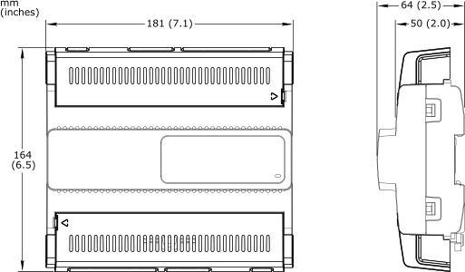
Optional covers
All RP-C models can be equipped with optional covers to reduce access to the screw terminals and wires.

RP-C with equipped with optional covers
Wireless connectivity
RP-C is a Bluetooth Low Energy (BLE) enabled product. You can use this wireless connectivity option to connect the RP-C with a smartphone or tablet running the Commission mobile application or the Engage mobile application for room comfort settings.
Through Wireless Adapter - Advanced connected to the host USB port, Zigbee TM wireless connectivity can be enabled for the RP controller. The controller can extend its point count through the Zigbee wireless network and bring flexibility in your applications. The RP controller equipped with the adapter is a Zigbee Certified Product that is compliant with Zigbee 3.0. For more information on the adapter and supported wireless devices, see the Wireless Adapter - Advanced Specification Sheet.
Advanced monitoring
The BACnet/IP controllers support local trends, schedules, and alarms, enabling local operation when the controller is offline or used in standalone applications.
The battery-free power backup of the memory and real-time clock helps prevent data loss and allows seamless and quick recovery after a power disruption.
In WorkStation, you update the firmware of multiple BACnet/IP controllers at the same time and with minimum down time. The EcoStruxure BMS server keeps track of the installed firmware to support backup, restore, and replacement of the controllers and sensors. The server can host controllers of different firmware versions.
Two configurable RS-485 ports
The RP-C controller has two configurable RS-485 ports, which can be configured to support three different types of networks:
Sensor bus
Room bus
Modbus network
The RP-C controller can run one of each network type.
One of the RS-485 ports can also be configured to support BACnet MS/TP network communication with the automation server, instead of BACnet/IP. For more information, see section “BACnet MS/TP support”. The other RS-485 port can then be configured to support either sensor bus, room bus, or Modbus network.
Sensor bus for living space sensors
The BACnet/IP controllers provide an interface designed for the SpaceLogic Sensor family of living space sensors. The SpaceLogic Sensor devices offer an efficient way to sense the temperature, humidity, CO 2 , and occupancy in a room. The SpaceLogic Sensor devices are available with different combinations of sensor types and various covers and user interface options, such as touchscreen, setpoint and override buttons, and blank covers.

SpaceLogic Sensor devices
The RP controller sensor bus provides both power and communications for up to four sensors that are daisy-chained using standard Cat 5 (or higher) cables. This maximum number of sensors that can be connected to a controller is regardless of the sensor model and the combination of cover and sensor base type:
Blank covers: Up to four sensors of any combination of sensor base types
3-button and touchscreen covers: Up to four sensors of any combination of sensor base types
SpaceLogic LCD temperature sensors: Up to four sensors are supported
The maximum total length of the sensor bus is 61 m (200 ft). For more information, see the SpaceLogic Sensors - SXWS Sensors for MP and RP IP Controllers - Specification Sheet.
Room bus for Connected Room Solutions
The RP controller room bus allows RP controller expansion modules to be connected to the controller for people counting, motion detection, luminosity and sound pressure level measurements, Bluetooth Low Energy based applications, and control of electric lights and window blinds.
The RP-C Advanced controller room bus supports up to six connected RP controller expansion modules with the following restrictions:
Maximum of two DALI light modules
Maximum of two SMI blind modules
Maximum of four Multi-sensor or Insight-Sensor devices
Maximum total length of the room bus is 72 m (236 ft).
For more information, see the Specification Sheets for the RP controller expansion modules.
Modbus RTU subnetwork
The RP controller Modbus network allows standard Modbus devices and the KNX Modbus gateway (RP-C-EXT-KNX) to be connected to the controller.
The Modbus RTU protocol is used for the communication. The RP controller acts the Modbus client and the connected devices act as servers.
The maximum number of Modbus devices that can be connected to an RP controller depends on the type of Modbus device and the number of Modbus registers.
The RP controller Modbus network supports up to 10 connected Modbus devices with the following restrictions:
Maximum of one KNX Modbus gateway (RP-C-EXT-KNX)
Maximum of 250 Modbus registers
The RP controller Modbus network does not support 64-bit Modbus registers.
KNX support
Through the KNX Modbus gateway (RP-C-EXT-KNX), the RP controller can communicate with KNX devices such as push-buttons and sensors.
The KNX Modbus gateway provides a KNX to Modbus interface that connects to one of the RP controller's configurable RS-485 ports.
For more information, see the RP-C-EXT-KNX Specification Sheet.
BACnet MS/TP support
The RP controllers support both BACnet IP and MS/TP protocols. The controller can be configured to use either protocol. This feature enables both retrofitting of MNB and b3 BACnet devices while reusing parts of the existing cabling and equipment, as well as a later transition from the BACnet MS/TP (RS-485) network to an IP based network.
An RJ45 to screw terminal block adapter is required to connect the RP controller to the BACnet MS/TP network of the AS-P or AS-B server. The adapter can be ordered from Schneider Electric. The adapter is available in two models, with an isolated or non-isolated RS-485 interface. For more information, see section “Part Numbers”.
To connect the adapter, it is recommended that you use a Cat 5 (or higher) UTP cable with eight conductors and RJ45 connectors. The cable should be rated for the target environment and have a maximum length of 0.3 m (12 in.). The cable is not included and needs to be purchased separately.
In retrofit projects with MNB devices, the RP controllers can be mixed with MNB devices on the BACnet MS/TP network. A mix of up to 50 devices per RS-485 Com port can be connected to an AS-P or AS-B server. The isolated adapter is used for connection of a controller. The adapter is connected to the RS-485 Com B port on the controller.
In retrofit projects with b3 BACnet devices, the RP controllers can be mixed with b3 BACnet devices on the BACnet MS/TP network. A mix of up to 50 devices per RS-485 Com port can be connected to an AS-P or AS-B server. The non-isolated adapter is used for connection of a controller. The adapter can be connected to either the RS-485 Com A or Com B port on the controller.
In retrofit projects with only RP controllers on the BACnet MS/TP network, up to 50 RP controllers per RS-485 Com port can be connected to an AS-P or AS-B server. The non-isolated adapter is used for connection of a controller. The adapter can be connected to either the RS-485 Com A or Com B port on the controller.
Engage mobile application
The Engage mobile application enables control of room temperature, fan speed, lights, and blinds/shades directly from a smartphone. A user can manage these settings when the application is connected to the RP controller.
The Engage mobile application is free and available for download from Google Play and Apple App Store.
For more information, see the Engage Specification Sheet.
Commission mobile application
The Commission mobile application is designed for local configuration, field deployment, and commissioning of BACnet/IP controllers. The mobile application reduces the commissioning time, allows flexibility in project execution, and minimizes dependencies on network infrastructure.
The mobile application is designed for use with Android, Apple (iOS), and Microsoft Windows 10 and Windows 11 devices. For more information, see the EcoStruxure Building Commission Specification Sheet.

Commission mobile application
Using the Commission mobile application, you can connect to one or many RP controllers. You can connect to a single RP controller using the controller's built-in Bluetooth connectivity or using the SpaceLogic Bluetooth Adapter connected to a SpaceLogic Sensor. Using a wireless access point or a network switch, you can connect to a network of RP controllers on the local IP network.
With the Commission mobile application, you can easily discover BACnet/IP controllers on the IP network. You can change the configuration of each controller, including the BACnet and IP network settings, location, and parent server. To save engineering time, you can save common device settings and then reuse them for controllers of the same model.
The Commission mobile application does not require an EcoStruxure BMS server or a network infrastructure to be in place. You can use the mobile application to load the controller application directly into the local BACnet/IP controller and deploy the controller. The controller application can be created offline using Project Configuration Tool or WorkStation. You can use the mobile application to change the behavior of an installed standard controller application, such as configuring temperature setpoints. You can also perform an I/O checkout to verify that the controller's I/O points are configured, wired, and operating correctly.
You can perform I/O checkout on the RP controller room bus to verify proper communication over the room bus between the RP controller and the associated RP controller expansion modules. Module type mismatches or address mismatches can then be resolved. After wiring the physical inputs and outputs of the RP controller expansion modules, you can perform the following tasks on the different modules:
DALI light modules: discover, wink, and associate DALI lights with the logical software points, and test individual lights
0-10V light modules: test individual lights
Blind modules: calibrate and test blinds
Relay module: test outputs
Full EcoStruxure Building Operation software support
The power of the RP controller is fully realized when it is part of an EcoStruxure BMS, which provides the following benefits:
WorkStation/WebStation interface
Script and Function Block programming options
Device discovery
Engineering efficiency
Preconfigured BMS applications for HVAC and Connected Room Solutions
Zoning option
WorkStation and WebStation provide a consistent user experience regardless of which EcoStruxure BMS server the user is logged on to. The user can log on to the parent EcoStruxure BMS server to engineer, commission, supervise, and monitor the BACnet/IP controller and its I/O as well as its attached SpaceLogic Sensor devices. For more information, see the WorkStation and WebStation specification sheets.
The fully programmable RP and MP controller models have both Script and Function Block programming options. Existing programs can easily be reused between the EcoStruxure BMS server and the controller.
The enhanced Device Discovery in WorkStation enables you to easily identify BACnet/IP controllers on a BACnet network and to associate the controllers with their parent server.
The engineering and maintenance of BACnet/IP controllers can be done very efficiently using the EcoStruxure Building Operation reusability features. With these features, you can create library items (Custom Types) for a complete controller application that contains programs and all necessary objects such as trends, alarms, and schedules. The controller application in the Custom Types library is reusable across all controllers of the same model. You can use the controller application as a base for creating new controllers intended for similar applications. You can then edit the controller application, and the changes are automatically replicated to all controllers, while each controller keeps its local values.
WorkStation supports both online and offline engineering of BACnet/IP controllers. You can make the configuration changes online or use database mode to make the changes offline. In database mode, the changes are saved to the EcoStruxure Building Operation database so that you can apply the changes to the controllers later.
Project Configuration Tool enables you to perform all the engineering off site, without the need for physical hardware, which minimizes the time you need to spend on site. You can run the EcoStruxure BMS servers virtually and engineer the BACnet/IP controllers before you deploy your server and controller applications to the servers and controllers on site. For more information, see the Project Configuration Tool specification sheet.
To improve engineering efficiency and standardize engineering practices, fully designed and tested controller applications are available at bms-applications.schneider-electric.com for use with the RP controllers. This library contains applications for different RP controller models and application types, such as fan coil units, ceiling solutions, lights and blinds. These preconfigured controller applications are packages that include all software programs, and for example graphics, alarms, and documentation such as functional specifications and I/O wiring schedules, that are needed for your projects. The online repository can be accessed using common web browsers on Windows PCs as well as mobile devices running Apple iOS 11.3 (or later) and Android 6.0 Marshmallow (or later).

Download page for preconfigured BMS applications
The Zoning option for WorkStation and WebStation provides access to an interactive zoning tool that enables easy reconfiguration of Connected Room Solutions and flexibility when switching between zones. The WebStation zoning tool provides a graphical interface that enables quick editing of zones from any web browser device.
The RP-C-12A, -12B, -12C, and -16A models support up to four segments, which can be used to support rezoning in a building.
Web services
The RP controller uses the RESTful API, which allows IT web services to easily interact with software applications. The flexibility of the RESTful API allows the RP controller to handle multiple types of input and return different data formats. With Web services, clients can read/write data (BACnet values) directly from/to the controller. Web services use resource methods GET, PUT, POST, and DELETE to access and use the data. HTTPS is used for communication between the client and the controller.
The Web services function is disabled by default. When enabled, it requires approximately 200 kB of RP controller memory.
|
Product |
Part number |
|
RP-C-12A-F-24V
|
SXWRCF12A10002
|
|
RP-C-12B-F-24V
|
SXWRCF12B10002
|
|
RP-C-12C-F-24V
|
SXWRCF12C10002
|
|
RP-C-16A-F-230V
|
SXWRCF16A10003
|
|
Optional covers
|
SXWRPCCOV10001
|
|
DIN-RAIL-CLIP, DIN-rail end clip
package of 25 pieces
|
SXWDINEND10001
|
|
Isolated RS-485 adapter
|
SXWISORS48510001
|
|
Non-isolated RS-485 adapter
|
SXWNISORS48510001
|
|
SpaceLogic Bluetooth Adapter
|
SXWBTAECXX10001
|
For the RS-485 adapters, contact a local Schneider Electric sales representative for product availability.
For more information on part numbers for Network Connectivity Accessories, see the For more information, see Product Selection Guide - EcoStruxure Building ..
Specifications
| AC input | |||||||||||||
| RP-C-12A-F-24V, RP-C-12B-F-24V, and RP-C-12C-F-24V | |||||||||||||
Nominal voltage
|
24 VAC
|
||||||||||||
Operating voltage range
|
+/-15 %
|
||||||||||||
Frequency
|
50/60 Hz
|
||||||||||||
Maximum power consumption
|
23 VA
|
||||||||||||
Power input protection
|
MOV suppression and internal fuse
|
||||||||||||
| RP-C-16A-F-230V | |||||||||||||
Nominal voltage
|
230 VAC
|
||||||||||||
Operating voltage range
|
+/-10 %
|
||||||||||||
Frequency
|
50/60 Hz
|
||||||||||||
Maximum power consumption
|
65 VA
|
||||||||||||
Power consumption without load
|
5 W
|
||||||||||||
Power input protection
|
MOV suppression and internal fuse
|
||||||||||||
Separate PTC thermistor used as a resettable fuse for 24 VAC Out only
|
|||||||||||||
Overvoltage category
|
III
|
||||||||||||
Pollution degree
|
2
|
||||||||||||
| DC input | |||||||||||||
| RP-C-12A-F-24V, RP-C-12B-F-24V, and RP-C-12C-F-24V | |||||||||||||
Nominal voltage
|
24 to 30 VDC
|
||||||||||||
Operating voltage range
|
23.5 to 33 VDC
|
||||||||||||
Maximum power consumption
|
14 W
|
||||||||||||
Power input protection
|
MOV suppression and internal fuse
|
||||||||||||
| AC output | |||||||||||||
| RP-C-16A-F-230V | |||||||||||||
Type
|
Isolated Class 2 output
|
||||||||||||
Nominal voltage
|
24 VAC
|
||||||||||||
Frequency
|
Same frequency as the power supply (50/60 Hz)
|
||||||||||||
Output power rating
|
19 VA
|
||||||||||||
| Environment | |||||||||||||
| RP-C-12A-F-24V, RP-C-12B-F-24V, and RP-C-12C-F-24V | |||||||||||||
Ambient temperature, operating
|
0 to 50 °C (32 to 122 °F) at normal operation
|
||||||||||||
-40 to +60 °C (-40 to +140 °F) for rooftop applications, horizontal installation only
|
|||||||||||||
Ambient temperature, storage
|
-20 to +70 °C (-4 to +158 °F)
|
||||||||||||
Maximum humidity
|
95 % RH non-condensing
|
||||||||||||
| RP-C-16A-F-230V | |||||||||||||
Ambient temperature, operating
|
0 to 50 °C (32 to 122 °F)
|
||||||||||||
Ambient temperature, storage
|
-20 to +70 °C (-4 to +158 °F)
|
||||||||||||
Maximum humidity
|
95 % RH non-condensing
|
||||||||||||
| Material | |||||||||||||
Plastic flame rating
|
UL94-5VB
|
||||||||||||
Ingress protection rating
|
IP 20
|
||||||||||||
| Mechanical | |||||||||||||
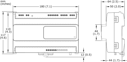
Dimensions
|
180 W x 110 H x 64 D mm (7.1 W x 4.3 H x 2.5 D in.)
|
||||||||||||
|
|||||||||||||
Weight, RP-C-12A-F-24V
|
0.370 kg (0.816 lb)
|
||||||||||||
Weight, RP-C-12B-F-24V and RP-C-12C-F-24V
|
0.390 kg (0.860 lb)
|
||||||||||||
Weight, RP-C-16A-F-230V
|
0.720 kg (1.587 lb)
|
||||||||||||
Weight, optional covers
|
0.070 kg (0.154 lb)
|
||||||||||||
Installation
|
DIN rail or flat surface
|
||||||||||||
Terminal blocks
|
Fixed
|
||||||||||||
| Optional covers | |||||||||||||
Dimensions
|
181 W x 164 H x 64 D mm (7.1 W x 6.5 H x 2.5 D in.)
|
||||||||||||
|
|||||||||||||
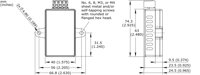
| Isolated and non-isolated RS-485 adapters (Optional) | |||||||||||||
DC input nominal voltage
|
Isolated adapter: 24 VDC
|
||||||||||||
Non-isolated adapter: 0 V
|
|||||||||||||
Maximum power consumption
|
Isolated adapter: 0.4 W
|
||||||||||||
Non-isolated adapter: 0 W
|
|||||||||||||
Dimensions
|
See drawing below
|
||||||||||||
|
|||||||||||||
Weight
|
Isolated adapter: 80 g (2.82 oz)
|
||||||||||||
Non-isolated adapter: 40 g (1.41 oz)
|
|||||||||||||
Installation, isolated adapter
|
Connection to RS-485 Com B via Cat 5 UTP cable (not included)
a
|
||||||||||||
Installation, non-isolated adapter
|
Connection to RS-485 Com A or Com B via Cat 5 UTP cable (not included)
a
|
||||||||||||
Installation options
|
The adapter can be fastened using screws or cable ties or mounted in line with a cable run.
a
|
||||||||||||
Approved for plenum installation (UL 2043)
|
|||||||||||||
| a) For more information, see the SpaceLogic RS-485 Adapter Installation Sheet. | |||||||||||||
Regulatory compliance and approvals
|
CE, UKCA, FCC, ISED (IC), UL 916, RCM, EU RoHS, WEEE, China RoHS
|
||||||||||||
| Compatibility | |||||||||||||
EcoStruxure BMS server communication
|
|||||||||||||
EcoStruxure Building Operation
|
version 3.0.1 and later
|
||||||||||||
BACnet MS/TP network support
|
|||||||||||||
EcoStruxure Building Operation
|
version 4.0.2 and later
|
||||||||||||
| Agency compliances | |||||||||||||
| RP-C-12A-F-24V, RP-C-12B-F-24V, and RP-C-12C-F-24V | |||||||||||||
Emission
|
RCM; BS/EN 61000-6-3; BS/EN 50491-5-2; FCC Part 15, Subparts B and C, Class B
|
||||||||||||
Immunity
|
BS/EN 61000-6-2; BS/EN 50491-5-3
|
||||||||||||
Radio
|
EN 300 328 V2.1.1
|
||||||||||||
Safety standards
|
BS/EN 60730-1; BS/EN 60730-2-11; BS/EN 50491-3; UL 916 C-UL US Listed
a
|
||||||||||||
| a) RP-C-12A is marked “Energy Management Equipment”. RP-C-12B and -12C are marked “Open Energy Management Equipment”. | |||||||||||||
FCC ID
|
DVE-RPC24
|
||||||||||||
ISED certification number
|
IC: 24775-RPC24
|
||||||||||||
Fire performance in air-handling spaces
a
|
UL 2043
|
||||||||||||
| a) The RP-C-12A, -12B, and -12C models are approved for plenum applications. | |||||||||||||
| RP-C-16A-F-230V | |||||||||||||
Emission
|
RCM; BS/EN 61000-6-3; BS/EN 50491-5-2
|
||||||||||||
Immunity
|
BS/EN 61000-6-2; BS/EN 50491-5-3
|
||||||||||||
Radio
|
EN 300 328 V2.1.1
|
||||||||||||
Safety standards
|
BS/EN 60730-1; BS/EN 60730-2-11; BS/EN 50491-3
|
||||||||||||
Energy
|
eu.bac Certified Product (Licence No. 219832); BS/EN 15500-1
|
||||||||||||
| Real-time clock | |||||||||||||
Accuracy, at 25 °C (77 °F)
|
+/-1 minute per month
|
||||||||||||
Backup time, at 25 °C (77 °F)
|
7 days minimum
|
||||||||||||
| Communication ports | |||||||||||||
Ethernet
|
Dual 10/100BASE-TX (RJ45)
|
||||||||||||
USB
|
1 USB 2.0 device port (mini-B)
|
||||||||||||
1 USB 2.0 host port (type-A), 5 VDC, 2.5 W
|
|||||||||||||
RS-485 port Com A
|
24 VDC, 3 W, RS-485 (RJ45)
|
||||||||||||
Transient voltage suppressors on communication and power signals
|
|||||||||||||
RS-485 port Com B
|
24 VDC, 3 W, RS-485 (RJ45)
|
||||||||||||
Transient voltage suppressors on communication and power signals
|
|||||||||||||
| Communications | |||||||||||||
BACnet
|
BACnet/IP, port configurable, default 47808
|
||||||||||||
BTL B-AAC (BACnet Advanced Application Controller)
a
|
|||||||||||||
| a) See the BTL Product Catalog for up-to-date details on BTL listed firmware revisions on BACnet International's home page. | |||||||||||||
| Wireless connectivity | |||||||||||||
| Bluetooth Low Energy | |||||||||||||
Communication protocol
|
Bluetooth
®
5.1 Low Energy compliant
|
||||||||||||
Frequency
|
2.402 to 2.480 GHz
|
||||||||||||
Maximum output power
|
10 dBm
|
||||||||||||
Maximum communication distance
|
Line-of-sight: 100 m (328 ft)
|
||||||||||||
Antenna
|
Integrated antenna
|
||||||||||||
RF connector for optional external antenna
|
SMA connector
|
||||||||||||
External antenna (optional)
|
Restricted to the approved antenna type listed below (used in certification)
|
||||||||||||
|
|||||||||||||
| CPU | |||||||||||||
Frequency
|
500 MHz
|
||||||||||||
Type
|
ARM Cortex-A7 single-core
|
||||||||||||
Internal SRAM
|
6 MB
|
||||||||||||
NOR flash memory
|
48 MB
|
||||||||||||
Memory backup
|
128 kB, FRAM, non-volatile
|
||||||||||||
| Universal inputs/outputs | |||||||||||||
Channels, RP-C-12A-F-24V
|
8 Ub, Ub1 to Ub8
|
||||||||||||
Channels, RP-C-12B-F-24V
|
8 Ub, Ub1 to Ub8
|
||||||||||||
Channels, RP-C-12C-F-24V
|
4 Ub, Ub1 to Ub4
|
||||||||||||
Channels, RP-C-16A-F-230V
|
8 Ub, Ub1 to Ub8
|
||||||||||||
Absolute maximum ratings
|
-0.5 to +24 VDC
|
||||||||||||
A/D converter resolution
|
16 bits
|
||||||||||||
Universal input/output protection
|
Transient voltage suppressor on each universal input/output
|
||||||||||||
| Digital inputs | |||||||||||||
Range
|
Dry contact switch closure or open collector/open drain, 24 VDC, typical wetting current 2.4 mA
|
||||||||||||
Minimum pulse width
|
150 ms
|
||||||||||||
| Counter inputs | |||||||||||||
Range
|
Dry contact switch closure or open collector/open drain, 24 VDC, typical wetting current 2.4 mA
|
||||||||||||
Minimum pulse width
|
20 ms
|
||||||||||||
Maximum frequency
|
25 Hz
|
||||||||||||
| Supervised inputs | |||||||||||||
5 V circuit, 1 or 2 resistors
|
|||||||||||||
Monitored switch combinations
|
Series only, parallel only, and series and parallel
|
||||||||||||
Resistor range
|
1 to 10 kohm
|
||||||||||||
| For a 2-resistor configuration, each resistor must have the same value +/- 5 % | |||||||||||||
| Voltage inputs | |||||||||||||
Range
|
0 to 10 VDC
|
||||||||||||
Accuracy
|
+/-(7 mV + 0.2 % of reading)
|
||||||||||||
Resolution
|
1.0 mV
|
||||||||||||
Impedance
|
100 kohm
|
||||||||||||
| Current inputs | |||||||||||||
Range
|
0 to 20 mA
|
||||||||||||
Accuracy
|
+/-(0.01 mA + 0.4 % of reading)
|
||||||||||||
Resolution
|
1 μA
|
||||||||||||
Impedance
|
47 ohm
|
||||||||||||
| Resistive inputs | |||||||||||||
10 ohm to 10 kohm accuracy
|
+/-(7 + 4 x 10
-3
x R) ohm
|
||||||||||||
| R = Resistance in ohm | |||||||||||||
10 kohm to 60 kohm accuracy
|
+/-(4 x 10
-3
x R + 7 x 10
-8
x R
2
) ohm
|
||||||||||||
| R = Resistance in ohm | |||||||||||||
| Temperature inputs (thermistors) | |||||||||||||
Range
|
-50 to +150 °C (-58 to +302 °F)
|
||||||||||||
| Supported thermistors | |||||||||||||
Honeywell
|
20 kohm
|
||||||||||||
Type I (Continuum)
|
10 kohm
|
||||||||||||
Type II (I/NET)
|
10 kohm
|
||||||||||||
Type III (Satchwell)
|
10 kohm
|
||||||||||||
Type IV (FD)
|
10 kohm
|
||||||||||||
Type V (FD w/ 11k shunt)
|
Linearized 10 kohm
|
||||||||||||
Satchwell D?T
|
Linearized 10 kohm
|
||||||||||||
Johnson Controls
|
2.2 kohm
|
||||||||||||
Xenta
|
1.8 kohm
|
||||||||||||
Balco
|
1 kohm
|
||||||||||||
| Measurement accuracy | |||||||||||||
20 kohm
|
-50 to -30 °C: +/-1.5 °C (-58 to -22 °F: +/-2.7 °F)
|
||||||||||||
-30 to 0 °C: +/-0.5 °C (-22 to +32 °F: +/-0.9 °F)
|
|||||||||||||
0 to 100 °C: +/-0.2 °C (32 to 212 °F: +/-0.4 °F)
|
|||||||||||||
100 to 150 °C: +/-0.5 °C (212 to 302 °F: +/-0.9 °F)
|
|||||||||||||
10 kohm, 2.2 kohm, and 1.8 kohm
|
-50 to -30 °C: +/-0.75 °C (-58 to -22 °F: +/-1.35 °F)
|
||||||||||||
-30 to +100 °C: +/-0.2 °C (-22 to +212 °F: +/-0.4 °F)
|
|||||||||||||
100 to 150 °C: +/-0.5 °C (212 to 302 °F: +/-0.9 °F)
|
|||||||||||||
Linearized 10 kohm
|
-50 to -30 °C: +/-2.0 °C (-58 to -22 °F: +/-3.6 °F)
|
||||||||||||
-30 to 0 °C: +/-0.75 °C (-22 to +32 °F: +/-1.35 °F)
|
|||||||||||||
0 to 100 °C: +/-0.2 °C (32 to 212 °F: +/-0.4 °F)
|
|||||||||||||
100 to 150 °C: +/-0.5 °C (212 to 302 °F: +/-0.9 °F)
|
|||||||||||||
1 kohm
|
-50 to +150 °C: +/-1.0 °C (-58 to +302° F: +/-1.8 °F)
|
||||||||||||
| RTD temperature inputs | |||||||||||||
Supported RTDs
|
Pt1000, Ni1000, and LG-Ni1000
|
||||||||||||
| Pt1000 | |||||||||||||
Sensor range
|
-50 to +150 °C (-58 to +302 °F)
|
||||||||||||
|
|||||||||||||
| Ni1000 | |||||||||||||
Sensor range
|
-50 to +150 °C (-58 to +302 °F)
|
||||||||||||
|
|||||||||||||
| LG-Ni1000 | |||||||||||||
Sensor range
|
-50 to +150 °C (-58 to +302 °F)
|
||||||||||||
|
|||||||||||||
| RTD temperature wiring | |||||||||||||
Maximum wire resistance
|
20 ohm/wire (40 ohm total)
|
||||||||||||
Maximum wire capacitance
|
60 nF
|
||||||||||||
| The wire resistance and capacitance typically corresponds to a 200 m wire. | |||||||||||||
| Voltage outputs | |||||||||||||
Range
|
0 to 10 VDC
|
||||||||||||
Accuracy
|
+/-60 mV
|
||||||||||||
Resolution
|
10 mV
|
||||||||||||
Minimum load resistance
|
2.4 kohm
|
||||||||||||
Source current
|
+4.2 mA
|
||||||||||||
Sink current
|
-1 mA (0 to 0.4 VDC)
|
||||||||||||
-4.2 mA (0.4 to 10 VDC)
|
|||||||||||||
| Relay outputs, DO | |||||||||||||
Channels, RP-C-12A-F-24V
|
0
|
||||||||||||
Channels, RP-C-12B-F-24V
|
3, DO1 to DO3
|
||||||||||||
Channels, RP-C-12C-F-24V
|
3, DO5 to DO7
|
||||||||||||
Channels, RP-C-16A-F-230V
|
3, DO5 to DO7
|
||||||||||||
Contact rating
|
Pilot Duty (C300)
|
||||||||||||
Resistive load: 250 VAC/30 VDC, 4 A (cos phi = 1)
|
|||||||||||||
Inductive load: 250 VAC/30 VDC, 4 A (cos phi = 0.4)
|
|||||||||||||
Switch type
|
Form A Relay
|
||||||||||||
Single Pole Single Throw
|
|||||||||||||
Normally Open
|
|||||||||||||
Commons
|
COM1 for DO1, DO2, and DO3 (on RP-C-12B model)
|
||||||||||||
COM3 for DO5, DO6, and DO7 (on RP-C-12C and RP-C-16A models)
|
|||||||||||||
Isolation contact to system ground
|
3,000 VAC
|
||||||||||||
Cycle life
|
At least 100,000 cycles
|
||||||||||||
Minimum pulse width
|
100 ms
|
||||||||||||
| High power relay outputs, DO | |||||||||||||
Channels, RP-C-12A-F-24V
|
0
|
||||||||||||
Channels, RP-C-12B-F-24V
|
1, DO4
|
||||||||||||
Channels, RP-C-12C-F-24V
|
1, DO8
|
||||||||||||
Channels, RP-C-16A-F-230V
|
1, DO8
|
||||||||||||
Contact rating
|
Pilot Duty (B300)
|
||||||||||||
Minimum current: 100 mA (5 VDC)
|
|||||||||||||
Normally Open contact, resistive load: 250 VAC/24 VDC, 12 A (cos phi = 1)
|
|||||||||||||
Normally Closed contact, inductive load: 250 VAC/24 VDC, 3 A (cos phi = 0.4)
|
|||||||||||||
Switch type
|
Form C Relay
|
||||||||||||
Single Pole Double Throw
|
|||||||||||||
Normally Open and Normally Closed
|
|||||||||||||
Isolation contact to system ground
|
5,000 VAC
|
||||||||||||
Cycle life
|
At least 100,000 cycles
|
||||||||||||
Minimum pulse width
|
100 ms
|
||||||||||||
| Solid-state relay outputs, DO | |||||||||||||
Channels, RP-C-12A-F-24V
|
4, DO1 to DO4
|
||||||||||||
Channels, RP-C-12B-F-24V
|
0
|
||||||||||||
Channels, RP-C-12C-F-24V
|
4, DO1 to DO4
|
||||||||||||
Channels, RP-C-16A-F-230V
|
4, DO1 to DO4
|
||||||||||||
Output rating
|
Maximum 2 A load per output
|
||||||||||||
Maximum 4 A total load for the 4 outputs
|
|||||||||||||
AC voltage range
|
Maximum 30 VAC
|
||||||||||||
DC voltage range
|
Maximum 30 VDC
|
||||||||||||
Commons
|
COM1 for DO1 and DO2 (on RP-C-12A, -12C, and -16A models)
|
||||||||||||
COM2 for DO3 and DO4 (on RP-C-12A, -12C, and -16A models)
|
|||||||||||||
| When the SSR outputs are used to switch AC, the common terminals can be connected to 0 to 30 VAC. When the SSR outputs are used to switch DC, the common terminals can be connected to -30 VDC to +30 VDC. | |||||||||||||
Common voltage range (AC)
|
0 to 30 VAC
|
||||||||||||
Common voltage range (DC)
|
-30 to +30 VDC
|
||||||||||||
Minimum pulse width
|
100 ms
|
||||||||||||
Solid-state relay output protection
|
Transient voltage suppressor across each solid-state relay (SSR) output
|
||||||||||||
Terminals
For more information on wiring, see Hardware Reference Guide.
")
RP-C-12A model (24 VAC/DC)
")
RP-C-12B model (24 VAC/DC)
")
RP-C-12C model (24 VAC/DC)
")
RP-C-16A model (230 VAC)
|
Product |
Part number |
|
Sensor base with temperature sensor |
SXWSBTXXXSXX |
|
Sensor base with temperature and humidity sensors |
SXWSBTHXXSXX |
|
Sensor base with temperature and CO 2 sensors |
SXWSBTXCXSXX |
|
Sensor base with temperature, humidity, and CO 2 sensors |
SXWSBTHCXSXX |
|
Product |
Housing |
Part number |
|
Blank cover |
Medium matte white |
SXWSCBXSELXX |
|
Blank cover |
Optimum glass white |
SXWSCBXSELXW |
|
Blank cover |
Optimum glass black |
SXWSCBXSELXB |
|
Blank cover with occupancy sensor |
Medium matte white |
SXWSCBPSELXX |
|
Blank cover with occupancy sensor |
Optimum glass white |
SXWSCBPSELXW |
|
Blank cover with occupancy sensor |
Optimum glass black |
SXWSCBPSELXB |
|
3-button cover |
Medium matte white |
SXWSC3XSELXX |
|
3-button cover |
Optimum glass white |
SXWSC3XSELXW |
|
3-button cover |
Optimum glass black |
SXWSC3XSELXB |
|
3-button cover with occupancy sensor |
Medium matte white |
SXWSC3PSELXX |
|
3-button cover with occupancy sensor |
Optimum glass white |
SXWSC3PSELXW |
|
3-button cover with occupancy sensor |
Optimum glass black |
SXWSC3PSELXB |
|
Touchscreen display cover |
Medium matte white |
SXWSCDXSELXX |
|
Touchscreen display cover |
Optimum glass white |
SXWSCDXSELXW |
|
Touchscreen display cover |
Optimum glass black |
SXWSCDXSELXB |
|
Touchscreen display cover with occupancy sensor |
Medium matte white |
SXWSCDPSELXX |
|
Touchscreen display cover with occupancy sensor |
Optimum glass white |
SXWSCDPSELXW |
|
Touchscreen display cover with occupancy sensor |
Optimum glass black |
SXWSCDPSELXB |
|
Touchscreen display cover with light control buttons |
Optimum glass white |
SXWSC2XSELXW |
|
Touchscreen display cover with light control buttons |
Optimum glass black |
SXWSC2XSELXB |
|
Touchscreen display cover with light control buttons and occupancy sensor |
Optimum glass white |
SXWSC2PSELXW |
|
Touchscreen display cover with light control buttons and occupancy sensor |
Optimum glass black |
SXWSC2PSELXB |
|
Touchscreen display cover with light and blind control buttons |
Optimum glass white |
SXWSC4XSELXW |
|
Touchscreen display cover with light and blind control buttons |
Optimum glass black |
SXWSC4XSELXB |
|
Touchscreen display cover with light and blind control buttons and occupancy sensor |
Optimum glass white |
SXWSC4PSELXW |
|
Touchscreen display cover with light and blind control buttons and occupancy sensor |
Optimum glass black |
SXWSC4PSELXB |
|
Product |
Housing |
Part number |
|
Complete SpaceLogic Sensor model with temperature sensor, buttons for override and setpoint control, and LCD display cover |
Medium matte white |
SXWSATXXXSLX |
|
Complete SpaceLogic Sensor model with temperature sensor, buttons for override and setpoint control, and LCD display cover |
Optimum glass white |
SXWSATXXXSLW |
|
Complete SpaceLogic Sensor model with temperature sensor, buttons for override and setpoint control, and LCD display cover |
Optimum glass black |
SXWSATXXXSLB |
|
Complete non-communicating a SpaceLogic Sensor model with resistive temperature sensor (10 kohm type 3 thermistor) and blank cover |
Medium matte white |
SLASXXX |
|
Complete non-communicating a SpaceLogic Sensor model with resistive temperature sensor (10 kohm type 3 thermistor) and blank cover |
Optimum glass white |
SLAWXXX |
|
Complete non-communicating a SpaceLogic Sensor model with resistive temperature sensor (10 kohm type 3 thermistor) and blank cover |
Optimum glass black |
SLABXXX |
- The SpaceLogic resistive temperature sensor (SLA...) is designed to be connected to I/O points/terminals on RP or MP controllers, or I/O modules. The sensor requires an analog input (temperature input).
Enterprise Server
AS-P
AS-B
WorkStation
WebStation
RP-C-EXT-MS-BLE
RP-C-EXT-IS-BLE
RP-C-EXT-DALI-M-PD
RP-C-EXT-DALI
RP-C-EXT-0-10V-4-PD
RP-C-EXT-0-10V-4
RP-C-EXT-BL-4-HV-PD
RP-C-EXT-BL-2-LV-PD
RP-C-EXT-BL-SMI-4-HV-PD
RP-C-EXT-BL-SMI-2-LV-PD
RP-C-EXT-REL-4
CRS-HH-REL-10
RP-C-EXT-KNX
Wireless Adapter - Advanced
RP-C-EXT-ZB-DALI
RP-C-EXT-ZB-0-10V
RP-C-RC-BLE
Commission
Engage
Project Configuration Tool
Automated Engineering Tool