
How to
Powering Up an RP-C 24 V Controller Model
You perform the following steps to power up an RP-C 24 V controller model.
The RP-C can be installed on a DIN rail or flat surface.
Rules and regulations
The RP-C must be professionally installed to comply with the following rules and regulations:
Part 15 of the Federal Communications Commission (FCC) rules
Innovation, Science and Economic Development Canada (ISED) licence-exempt Radio Standards Specifications (RSSs)
2014/53/EU Radio Equipment Directive (RED) of the European Union (EU)
S.I. 2017/1206 - Radio Equipment Regulations 2017 of the United Kingdom (UK)
For more information, see RP-C Regulatory Compliance and Approvals .
The RP-C and its antenna(s) must be installed to provide a separation distance of at least 20 cm (8 in.) from all persons and must not be co-located or operating in conjunction with any other antenna or transmitter. Information on recommended RF exposure limits can be obtained from Health Canada's website, www.canada.ca/en/health-canada .
Installation orientation restrictions
The restrictions on installing the device in other orientations differ between the different RP-C controller models. For more information, see RP-C Models .
Under normal operating conditions of 0 to 50 °C (32 to 122 °F), the RP-C 24 V controller models can be installed in the following orientations:
Horizontally (on a DIN rail going from left to right), with the device label text in the upright position reading left to right. See “a” in the following figure.
Vertically (on a DIN rail going from top to bottom), which means that the device is rotated +90 degrees or -90 degrees from the horizontal position. See “b” and “c” in the following figure.
Face down from a ceiling. See “d” in the following figure.
Face up on a horizontal surface. See “f” in the following figure.
The only installation orientation that is not supported for the RP-C 24 V controller models is when the device is rotated 180 degrees from the horizontal position, that is, with device label text up and down. See “e” in the following figure. In the up and down position, the controller's thermal specifications may be exceeded, which can damage the controller.
")
Installation orientation restrictions for RP-C 24 V controller models operated in normal conditions, 0 to 50 °C (32 to 122 °F)
When the RP-C 24 V controller models are used for rooftop applications, -40 to +60 °C (-40 to +140 °F), the device should be installed horizontally, with the device label text in the upright position reading left to right. See “a” in the following figure. Any other installation orientation (“b”, “c”, “d”, “e”, and “f” in the figure) may exceed the controller's thermal specifications, which can damage the controller.
")
Installation orientation restrictions for RP-C 24 V controller models operated at -40 to +60 °C (-40 to +140 °F)
Under normal operating conditions of 0 to 50 °C (32 to 122 °F), the RP-C 230 V controller models can be installed in the following orientations:
Horizontally (on a DIN rail going from left to right), with the device label text in the upright position reading left to right. See “a” in the following figure.
Vertically (on a DIN rail going from top to bottom), which means that the device is rotated +90 degrees or -90 degrees from the horizontal position. See “b” and “c” in the following figure.
Installing the RP-C 230 V controller models rotated 180 degrees from the horizontal position is not supported. See “e” in the following figure. Installing the RP-C 230 V controller models face down from a ceiling (“d” in the figure) or face up on a horizontal surface (“f” in the figure) is only supported in the operating temperature range 0 to 40 °C (32 to 104 °F), but not in the temperature range 0 to 50 °C (32 to 122 °F). Installing the controller in an orientation that is not supported may cause the controller's thermal specifications to be exceeded, which can damage the controller.
")
Installation orientation restrictions for RP-C 230 V controller models operated in normal conditions, 0 to 50 °C (32 to 122 °F)
Installation on a DIN rail
A DIN rail is a common and convenient technique for installing the RP-C controller along with other associated control and monitoring devices. The most efficient ventilation is achieved with the wall-mounted DIN rail oriented horizontally and with adequate space provided between the RP-C rail and adjacent rails or other devices.
The RP-C controller is typically installed horizontally (on a DIN rail going from left to right), with the device label text in the upright position reading left to right.

Example of an RP-C controller installed on a horizontal DIN rail

RP-C controllers installed on horizontal DIN rails in a cabinet
When installing RP-C controllers in a cabinet, it is recommended to provide ample space between the DIN rails and controllers for sufficient ventilation.
To help prevent the device from sliding down or sideways on the DIN rail, install an end clip for DIN 35 (part number SXWDINEND10001) tightly against the bottom or rightmost device on the rail. The end clip is easily removed if you bend the snap lock open with a screwdriver.

End clip for DIN 35 fixed across the DIN rail
All RP-C controller models have fixed screw terminals.
The RP-C controller has four anchor points that can be used to fasten cable ties or other accessories for bundling wires.

Anchor points for cable ties

The RP-C controller comes in six different models, which offer five different combinations (sets) of I/O point types and CPU types. Four of the RP-C controller models support 24 VAC/DC input power and two of the models support 230 VAC.
RP-C 24 V controller models:
RP-C-12A-F-24V, RP-C-12B-F-24V, RP-C-12C-F-24V, and RP-C-16B-F-24V
RP-C 230 V controller models:
RP-C-16A-F-230V and RP-C-16B-F-230V

RP-C model number structure
|
Range |
Model |
I/O–CPU Set |
I/O Points |
CPU Type |
RAM / Flash Memory |
Input Power |
|
Advanced |
RP-C-12A-F-24V
|
12A |
12 |
ARM Cortex-A7 single-core
|
6 MB / 48 MB |
24 VAC at 50/60 Hz or 24 to 30 VDC |
|
Advanced |
RP-C-12B-F-24V |
12B |
12 |
ARM Cortex-A7 single-core
|
6 MB / 48 MB |
24 VAC at 50/60 Hz or 24 to 30 VDC |
|
Advanced |
RP-C-12C-F-24V |
12C |
12 |
ARM Cortex-A7 single-core
|
6 MB / 48 MB |
24 VAC at 50/60 Hz or 24 to 30 VDC |
|
Advanced |
RP-C-16A-F-230V |
16A |
16 |
ARM Cortex-A7 single-core
|
6 MB / 48 MB |
230 VAC at 50/60 Hz |
|
Pro |
RP-C-16B-F-24V |
16B |
16 |
ARM Cortex-A7 dual-core
|
128 MB / 64 MB |
24 VAC at 50/60 Hz or 24 to 30 VDC |
|
Pro |
RP-C-16B-F-230V |
16B |
16 |
ARM Cortex-A7 dual-core
|
128 MB / 64 MB |
230 VAC at 50/60 Hz |
For more information, see RP-C Onboard I/O .
For more information, see RP-C Built-in Power Supply .
All RP-C models have the same small footprint.
Differences Between RP-C Hardware Versions
There are a number of differences in hardware between different hardware versions of the RP-C-12A-F-24V, RP-C-12B-F-24V, RP-C-12C-F-24V, and RP-C-16A-F-230V controller models.
For more information, see Differences Between RP-C Hardware Versions .
Check that all wiring is correct.
Ensure that appropriate cable strain relief is provided, especially for wires that carry 30 VAC or 42.4 VDC or above.
You can use the anchor points on the controller enclosure and cable ties to fasten and fix the cables.
Ensure that the 24 VAC at 50/60 Hz or 24-30 VDC power is supplied to terminals 1 and 2.
action_zoom_plus_stroke 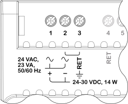
Ensure that the ground cable is connected to terminal number 3.
After powering up, check that the Status LED changes as follows:
Bluetooth interface enabled (default): Flashing blue/green light (Normal operation, Bluetooth advertising)
Bluetooth interface disabled: Constant green light, after about a minute (Normal operation, No Bluetooth activity)
For more information, see RP-C LEDs .
 RP-C Device Installation
RP-C Models
RP-C Screw Terminals
RP-C-12A-F-24V Screw Terminals
RP-C-12B-F-24V Screw Terminals
RP-C-12C-F-24V Screw Terminals
RP-C-16B-F-24V Screw Terminals
RP-C LEDs
RP-C Device Installation
RP-C Models
RP-C Screw Terminals
RP-C-12A-F-24V Screw Terminals
RP-C-12B-F-24V Screw Terminals
RP-C-12C-F-24V Screw Terminals
RP-C-16B-F-24V Screw Terminals
RP-C LEDs
 Status LEDs